Code Review & Dynamic Fuzzing of Microsoft’s Signing Transparency
Security Assessment of Microsoft’s Signing Transparency (ST)
IOActive performed a thorough security assessment of Microsoft’s Signing Transparency (ST) service, focusing on code review, dynamic analysis, and fuzz testing which is designed for use on Azure and is built on the Confidential Consortium Framework (CCF). Conducted from April to June 2025, the evaluation confirmed strong implementation security, secure integration, and compliance with ST’s objectives. Three informational findings suggested defence-in-depth improvements, and one medium-risk issue was resolved during the assessment. ST met its security commitments, though some assurances depend on hardware, system secrets, and users that were outside the scope.
Cybersecurity programs are under increasing pressure to demonstrate measurable efficacy, deliver value, and align with governance expectations—while operating under tight cost constraints. Return on Spend (ROS) and Return on Security Investment (ROSI) have become essential metrics for justifying and sustaining initiatives. This presentation evaluates program performance through the lens of Threat Analysis and Risk Assessment (TARA), drawing on insights from surveys of OEMs, Tier 1 suppliers, tool providers, regulators, fleets, and industry experts.
The study highlights recurring challenges of consistency, quality, and organizational maturity that limit the effectiveness of TARAs, often preventing them from functioning as true safety-critical safeguards. By applying proven process improvement disciplines, such as Lean, Six Sigma, and business process modeling, organizations can modernize their workflows, align with governance objectives, reduce costs, and enhance continuous risk management.
Attendees will gain practical strategies for improving program governance, leveraging performance metrics, and optimizing processes to maximize the ROI of cybersecurity operations. The objective is clear: deliver faster, smarter, and more resilient cybersecurity that drives both safety and business value across the ecosystem.
About the Presenter
Urban Jonson is a co-founder of SERJON (www.serjon.com) and a frequent collaborator with IOActive. Urban is a cybersecurity industry leader and serves in multiple advisory roles, including SAE International, TMC, ESCAR USA, CyberTruck Challenge, and as a cybersecurity expert for FBI InfraGard and the FBI Automotive Sector Working Group.
The semiconductor industry uses a large and complex set of jargon. This set of terms represents the significant intersection of scientific and engineering disciplines in this complex, high-technology industry, including chemistry, physics, material science, electrical engineering, industrial engineering, computer science, and others. However, this jargon can make the industry impenetrable to individuals who must manage the business impacts, cybersecurity consequences, and comprehensive risk to which the industry’s products expose organizations.
In our eGuide on silicon security, we ended with a glossary to aid those readers who may have limited exposure to this industry, in an attempt to make that critical material accessible to laypersons and experts alike while maintaining reasonable accuracy and precision. Our objective was to create short, accurate definitions that are accessible to the layperson, while any subject matter expert (SME) would not say they are wrong. There are absolutely more comprehensive, rigorous explanations of each of these terms, but they reinforce the inaccessibility of the material to non-expert individuals.
We are making these definitions available here in blog format to make them more accessible than they were when buried at the end of a PDF document. We welcome readers to suggest additional terms or clarifications to these definitions to support better decision-making by non-experts.
Broad-beam Ion Mill – A device used to ablate samples, such as microchips and ICs, with a beam of ions.
Conductor – A material which provides limited resistance to the flow of electric charge.
CPU – Central Processing Unit.
Dielectric – See Insulator.
Dual Beam – A workstation combing the functions of the FIB and SEM into a single device that allows for both imaging and editing a microchip or IC without moving the sample between workstations of different types, to improve efficiency and reduce the risk of sample contamination.
FIB – Focused Ion Beam. A technical workstation used to make modifications to a microchip or IC with a beam of ions.
Fuse – Also called an efuse. One-time-programmable (OTP) memory in which write operations are irreversible. Often used to store secure boot keys, permanently disable debug features, etc.
Gate – A core component of a transistor.
I/O – Input/Output.
IC – Integrated Circuit. A small electronic device that contains many interconnected electronic components on a single semiconductor chip.
ILD – Interlayer dielectric. An insulator separating two adjacent layers of wiring.
Insulator – A material which resists or inhibits the flow of electric charge.
Logic Cell – A digital circuit containing several transistors which performs a basic logical function, such as a Boolean AND or OR.
Microchip – An IC device manufactured using semiconductor material with layers of electronic components used to process or store information. Also referred to as a chip, computer chip, or IC.
Microcontroller – A single-chip device containing a CPU, RAM, ROM, and I/O peripherals. These are normally used in single-task applications and do not require an operating system.
Microprocessor – A standalone processing unit used in general-purpose computing tasks. These units require external components like memory and peripherals. These normally run an operating system.
Node – See Process Node.
Process Node – A vendor-specific semiconductor manufacturing process and associated design rules. Generally, in the past the node name referenced the feature size of components that could be manufactured with the process. Today the number in the node name no longer tightly corresponds to feature size.
RAM – Random-Access Memory.
Reactive Ion Etching – A type of dry etching with different characteristics than wet etching, which uses chemically reactive plasma to remove material from a target.
RIE – Reactive Ion Etcher.
ROM – Read-Only Memory.
Root of Trust (RoT) – A source that is intended to always be trusted within a system. Generally, these systems utilize cryptography to enable integrity, confidentiality, and authentication within the system.
Secure Boot – A security feature intended to protect a device’s integrity during the boot or startup process by verifying cryptographic signatures of the operating system and bootloader.
Secure Element – An integrated hardware and software component in an IC intended to protect against software and hardware attacks and isolate high-consequence data like a root of trust or cryptographic material.
SEM – Scanning Electron Microscope.
Semiconductor – A unique class of materials which is not exclusively a conductor or insulator.
Technology Node – See Process Node.
TEE – Trusted Execution Enclave. A protected area of a microprocessor’s memory and CPU intended to keep data and code secure.
Transistor – The fundamental component in ICs that controls (switches) the flow of electrical current between two terminals: the source and drain.
Vulnerability – A security defect that is present and exploitable in an environment.
INSIGHTS | September 17, 2025
Deepfake Defense: From No-Cost Basics to Enterprise-Grade Controls
By
Dave Falkenstein
At CanSecWest 2025 I walked through a red team where we used AI voice cloning to test an organization’s people and processes. The short version is this: a familiar voice is not identity. Treat voice as untrusted input and move verification into systems you control.
The financial exposure is no longer hypothetical. Deloitte estimates fraud losses in the United States could reach 40 billion dollars by 2027 as generative AI accelerates vishing and synthetic media.
Recent incidents back this up, including the 25 million dollar Hong Kong video-call heist tied to a deepfake of company leaders, and the Ferrari CEO impersonation attempt that an employee stopped by asking a question only the real executive could answer. Outside the enterprise, deepfake investment ads continue to run across Meta platforms, which erodes trust in familiar faces and voices your employees see every day. In government, an AI voice impersonating the U.S. Secretary of State contacted foreign ministers and U.S. officials in June 2025. Both trends increase the chance that urgency and authority will be misread as authenticity.
What changed
Cloning a usable voice takes seconds of public audio and commodity tools. On the receiving end, most victims are reached by phone or collaboration apps, not polished video. The attacker leans on urgency, hierarchy, and insider context, then pushes to finish before the target can shift to a verified process. The fix is a workflow that forces that shift.
Caller ID helps less than many expect. STIR/SHAKEN can authenticate numbers on IP networks, but it is not proof of who is speaking, and non-IP gaps are still being addressed by the FCC. Treat attestation as a helpful signal, not a decision.
The most targeted roles are accounts payable, vendor management, helpdesk, executive assistants, and HR. If you only harden one slice of the company, start there. Make it clear those teams can slow or refuse requests that arrive by phone or ad-hoc video without any penalty.
How the scam runs in practice
Attackers harvest voice and context from interviews, talks, and social videos. They start a call or meeting that looks routine, often with a look-alike number, and ask for a payment, a vendor add, or a credential reset.
If questioned, they add pressure and a sense of urgency by claiming a change needs to be made immediately for access to a meeting. The goal is to keep you in the real-time channel where social pressure works, and logging is weak. Your goal is to move the request into a tracked system where identity is verified, and more than one person approves.
Meeting platforms are part of the story too. Treat unscheduled or “special” meetings the same way as calls. Use lobbies and named invites. If a meeting requests a payment, an entitlement change, or a vendor add, move it into the approval system and end the call.
Controls by maturity
Entry level
Ban voice-only approvals. No payments, access changes, or identity changes are executed from calls or voicemails. Put the request into a ticket or approval flow first.
Directory callback only. If “the CFO” calls, hang up and call back using the corporate directory contact, not the inbound number.
One-time challenge in a second channel. Send a short code in Slack or Teams and have the caller read it back. Avoid static passphrases that can leak.
Plain-language script. “Per policy I am moving this into our approval workflow and calling you back on the directory number. I will send you a code in Slack in 10 seconds.”
Show what fakes sound like. With consent, let staff hear an internal clone so they learn what “good enough” fakery sounds like. Realtime voice clones and Text to speech voice clones will each have differing levels of quality that can be picked up on.
Bank instruction rule. Publish a standing rule that your bank instructions never change by phone or email. Put that statement on invoices and vendor onboarding materials so finance has a clear policy to point to.
Mid-maturity
Cross-channel confirmation by default. Every sensitive request is confirmed in a second, logged channel and attached to a ticket or approval artifact.
Approvals inside Slack or Teams. Use Microsoft Teams Approvals or Power Automate for sequential and multi-stage approvals, or Slack Workflow Builder for routed approvals with an audit trail.
Surface STIR/SHAKEN as a signal. If your carrier exposes attestation, show it in softphones and train that it is advisory, not identity.
Target training. Focus on AP, vendor management, helpdesk, executive assistants, and HR.
Lock down account recovery. Do not allow phone-based resets or knowledge questions for admins, finance approvers, or identity administrators. Require device-bound authenticators or passkeys and route all recovery into a ticket with second-party approval.
Enterprise-grade
Multi-party, cross-function approvals. Require at least two approvers from different functions for wires, new vendors, privileged access, and identity changes. Build this into Teams or Slack plus your ticketing or ERP.
Timed holds for high-risk actions. Add a 2 to 24 hour hold for first-time payees, large payments, and new vendors. Require re-affirmation during the hold.
Telco posture with specifics. Ask providers about STIR/SHAKEN coverage and expose attestation in your tooling. Track FCC work to close non-IP gaps and treat caller authentication as one input among many.
Executive exposure management. Where practical, limit long, clean public voice samples, and trim long monologues into shorter clips.
Incident response if you suspect a deepfake call
End the live channel and move to policy. Open a ticket, freeze any pending payment or access change, and notify finance leadership and security. If the window for a bank recall exists, contact your bank immediately. Save call metadata and collaboration logs. If recording calls is part of your workflow, make sure you follow local consent laws.
Do we need a deepfake detector?
Use detectors as a signal, not a gate. Accuracy varies in the wild, especially with compressed audio and human-in-the-loop attackers. Directory callbacks, second-channel challenges, multi-party approvals, and timed holds are what stop losses when detection misses.
Conclusion
Deepfakes are a forcing function for better workflow. Start by removing voice-only approvals and requiring directory callbacks and second-channel challenges. Add routed approvals inside Slack or Teams. For high-risk actions, require multiple approvers and a hold. If a perfect clone calls, these controls still give your team time to slow down and verify before money moves.
About the Author
Dave Falkenstein, Red Team Tech Lead, IOActive. Based on the CanSecWest 2025 talk “Deepfake Deception: Weaponizing AI-Generated Voice Clones in Social Engineering Attacks.”
Additional Resource
The Wall Street Journal | IOActive Senior Security Consultant David Falkenstein and The Wall Street Journal recently collaborated to create a quiz that looks to test if “your ears [can] distinguish a human voice from an AI deepfake…”
David was able to use AI to clone The Wall Street Journal colleagues sourced from publicly available social media clips and used OpenAudio to help run the experiment.
“Can your ears distinguish a human voice from an AI deepfake? Knowing the difference could save you from a phone scam that costs you thousands of dollars. …
… To test this, we enlisted David Falkenstein of corporate security firm IOActive to clone a few Wall Street Journal colleagues. He pulled down bits of our publicly available social-media and podcast audio, clips just 10 to 30 seconds in length. He used OpenAudio—easily accessible software that can run on a laptop—to make our voices say some pretty crazy things.”
INSIGHTS | July 31, 2025
Characterizing the Raspberry Pico 2 FI countermeasures – Part 1
By
Ramiro Pareja Veredas
Let’s start by saying that the Pico 2 – or more specifically, the RP2350 MCU – is an impressive chip. It’s powerful, packed with peripherals and features (I love the PIO!), easy to use and develop with, and from a security standpoint, exceptionally well designed.
After more than 10 years in chip security evaluations, I can confidently say that the RP2350 might be one of the most secure general-purpose, off-the-shelf MCUs on the market. I’ve evaluated enough chips to recognize when a system-on-chip (SoC) was designed with security in mind from the very beginning – integrating protection mechanisms early in the design phase – versus when security is treated as an afterthought, patched in late just to meet the minimum requirements. There’s no doubt: security was a top priority during the development of the RP2350.
The Raspberry Pi Foundation, clearly confident in their product, launched a bug bounty program offering €10,000 to the first person who could extract a secret stored in the Pico 2’s fuses. After a month without any successful claims, they doubled the reward to €20,000. To my knowledge, this is the first time a silicon developer has offered such a bounty – a commendable move.
That confidence is rooted in the chip’s well-engineered Secure Boot process and an effective glitch detector – both of which were tested extensively for months by two independent security firms prior to release. Still…it’s not perfect.
In January 2025, four winners for the challenge were announced, including IOActive’s Silicon Security team, which uncovered a novel method to invasively extract secrets from the RP2350 antifuse OTP. By leveraging a focused-ion-beam (FIB) microscope with passive voltage contrast (PVC), IOActive demonstrated an attack that challenges the long-standing assumption that antifuses are physically unreadable – posing a serious threat to any secure design that relies on them.
In addition to this invasive technique, this post – and those that follow – will document IOActive’s efforts to use fault injection (FI) to glitch and bypass the security protections of the Pico 2. This article assumes that the reader already has a basic understanding of fault injection. If not, I recommend reading up on the topic before proceeding.
Note: At the time this article was originally written (October 2024), the results of the Raspberry Pico 2 challenge were not yet published. This article has been updated in July 2025 to refer to those hacks.
The glitch detector
The RP2350 implements four glitch detectors, described in the datasheet as follows:
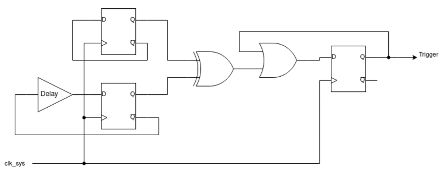
Figure 1. RP2350 glitch detector
The idea behind these detectors is straightforward: the output of two D-latches is XORed to detect differences. If a glitch is injected, it may flip the state of only one of the latches, immediately triggering the detector. To detect glitches that could flip both latches, a delay is inserted in the feedback path of one of the latches. If the glitch flips both D-latches simultaneously, the delayed feedback would force the latches to take on different values on the next clock cycle and the detector would be triggered.
Each of the four detectors can be independently configured via the GLITCH_DETECTOR.SENSITIVITY register or the OTP fuse CRIT1.GLITCH_DETECTOR_SENS. There are four sensitivity levels available, allowing fine-tuned detection based on the expected operating environment.
When a glitch is detected, the GLITCH_DETECTOR.TRIG_STATUS register indicates which of the detectors were triggered. If the glitch detectors are armed – either by writing to the GLITCH_DETECTOR.ARM register or by programming the OTP fuse CRIT1.GLITCH_DETECTOR_ENABLE – a reset is asserted automatically upon detection. In such cases, the HAD_GLITCH_DETECT bit in the POWMAN.CHIP_RESET register is set, indicating that the last reset was caused by the glitch detector.
Interestingly, it’s possible to monitor the output of the glitch detectors without triggering a reset – a feature that proves very useful when characterizing the detectors and tuning glitch parameters during testing.
The fact that the chip includes only four glitch detectors raises an important question: how resilient is this design against localized fault injection? It’s clear that a focused laser fault injection (L-FI) attack should bypass these detectors. This has been demonstrated by the winner of the Pico2 challenge, Kévin Courdesses, who modified an OpenFlex microscope to inject laser glitches.
But what about more common localized FI methods, like electromagnetic fault injection (EMFI) or body-bias injection (BBI)? That’s something we’ll explore in a future post, but Thomas Roth has already demonstrated that such an attack is feasible.
Characterizing the CPU with crowbar glitching
The first step in our evaluation was to assess the CPU’s sensitivity to voltage glitches. For this initial fault injection (FI) campaign, we disabled all glitch detectors – setting the sensitivity level to 0 and not arming them – in order to observe the CPU’s raw behavior without any interference from built-in protections and countermeasures.
For the glitching technique, we opted for crowbar switching, one of the most widely used methods in voltage fault injection. Its popularity stems largely from the simplicity and affordability of the hardware required. However, crowbar switching also offers technical advantages over other voltage glitching methods, which we’ll discuss later. In future posts, we’ll also cover results obtained using a DAC to generate voltage glitches and compare the two approaches in terms of effectiveness and control.
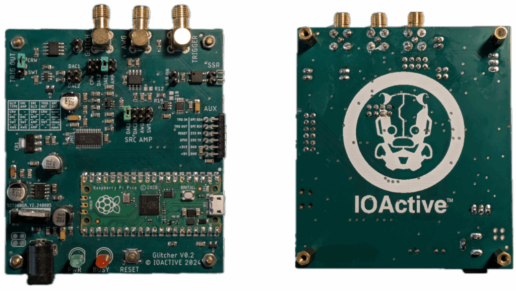
To inject the glitches, we used a tool called Glitch.IO. This tool is an in-house development based on the Raspberry Pi Pico, like many other glitchers, but with several unique features not previously seen in similar tools. Some of these unique features will be introduced throughout this series of posts. The Glitch.IO will be released as open hardware soon during Black Hat USA 2025.
Figure 2. Glitch.IO
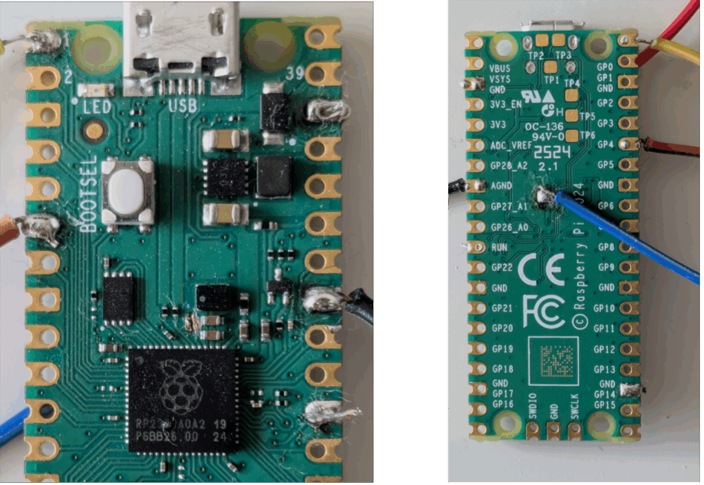
Modifying the Pico2 board
Before performing glitching experiments on the Raspberry Pi Pico 2, we first needed to modify the board to isolate the CPU power plane and remove its associated capacitance.
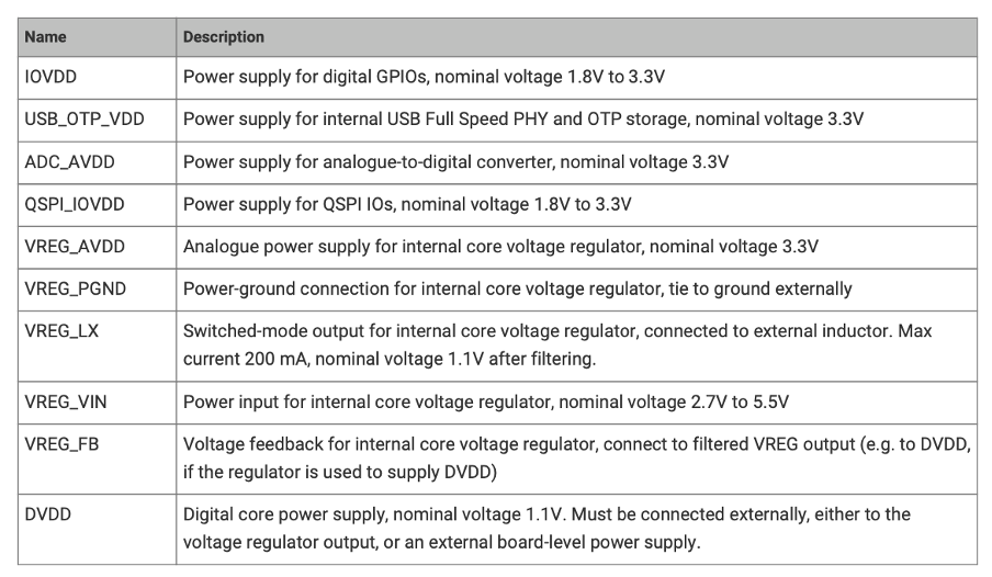
According to the datasheet (see Figure 3), the RP2350 features five power supply domains. However, only one is relevant for our purposes: DVDD – the 1.1V rail that powers the CPU core. This is the supply line where we’ll be injecting our glitches. The remaining power supplies operate at 3.3V and are not initially of interest for this stage of testing.
Note: Aedan Cullen – the third winner of the Pico2 challenge – found that the USB_OTP_VDD power rails is also interesting for glitching. I recommend his presentation at the 38C3.
Figure 3. Power supply pin description
To reduce the bill of materials (BOM) and facilitate the PCB design, the RP2350 chip has an integrated Switched-Mode Power Supply (SMPS ) that can generate the 1.1V from the 3.3V rail.
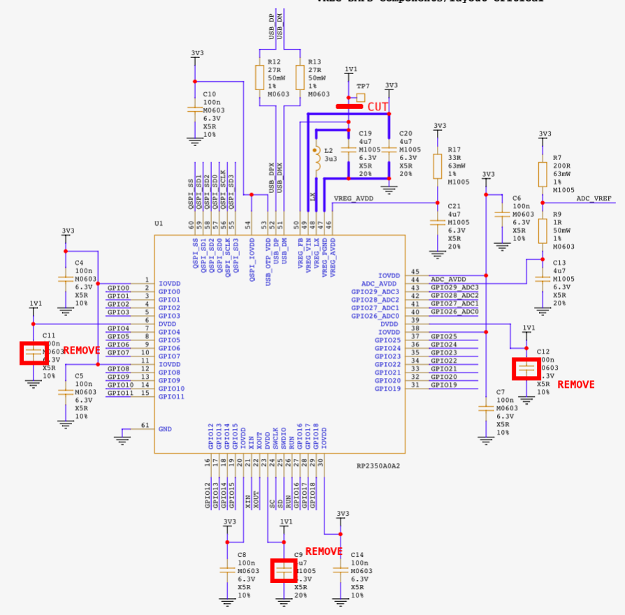
Referring to the Raspberry Pi Pico 2 schematics (available as an annex in the datasheet), we identified the decoupling capacitors on the DVDD power plane: C9, C11, and C12. These were removed to reduce the capacitance on the DVDD line, making the PCB more susceptible to glitches. Additionally, since we plan to perform DAC-based glitching and supply custom voltage profiles to the core, we had to isolate the DVDD pins from the SMPS output. To do this, we cut the trace connecting the 1.1V line to VREG_FB, effectively decoupling the internal regulator. We then supplied power directly to the DVDD rail using test point TP7 and an external power supply.
Figure 4 shows all of the modifications done in the schematic, and Figure 5 shows those modifications on the PCB.
Figure 4. Modifications in the schematic
Figure 5. Raspberry Pico 2 modified for FI
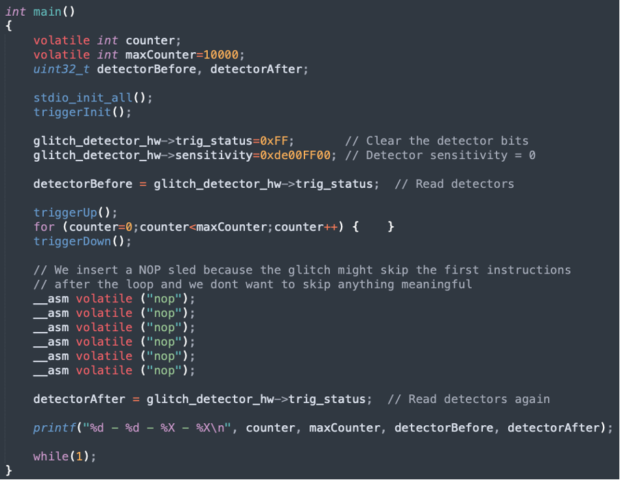
The test application
To characterize the target, we developed a standard “for loop” test application, shown in Figure 6, that will run on the Raspberry Pico 2. Before entering the loop, the glitch detectors are configured. After the loop is completed, the application prints the status of the detectors.
The goal of this fault injection (FI) campaign is to determine the optimal glitch parameters that can disrupt the execution of the loop without triggering the glitch detectors.
Figure 6. For loop characterization test application
The glitch application
The glitching tool must run an application responsible for four key tasks:
1. Preparing the target device for glitching
2. Waiting for a trigger
3. Injecting the glitch
4. Evaluating the target’s response and the glitch’s effects
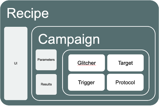
The Glitch.IO SDK simplifies the development of such applications. It provides a collection of modular classes designed to abstract and streamline the glitching process:
Glitchers: Implement different glitching techniques, such as crowbar, DAC-generated glitches, clock glitches, reset glitches, and MUX switching.
Triggers: Define how glitches are synchronized, supporting a variety of trigger sources (e.g., GPIO rise/fall, reset lines, UART RX/TX).
Protocols: Implement generic communication protocols like SWD, JTAG, etc.
Targets: Define the specific attack or test logic – for example, attacking secure boot, bypassing debug protections, or characterizing glitch sensitivity.
These components are instantiated and combined to form a “recipe” – an application that implements a specific attack on a specific device. Figure 7 represents the software architecture of a Glitch.IO application, and the following code shows the recipe used to characterize the Raspberry Pico 2.
In this recipe, glitch parameters and their variation strategies are defined in initializeParameters(). In main(), we instantiate and wire together the glitcher, trigger, and target components.
The Glitch.IO SDK also includes example recipes for common FI attacks against popular MCUs from vendors like NXP and ST – making it easy to get started with real-world targets.
The FI campaign
The glitch detectors in the RP2350 can be configured at four different sensitivity levels. For each level, we ran a series of FI campaigns: starting with broad glitch parameter sweeps and then progressively narrowing them down in an attempt to maximize the success rate – defined as glitches that disrupt execution without being detected.
Throughout the campaigns, we logged two key outcomes:
Whether the glitch was successful (i.e., it altered the behavior of the for loop).
Which glitch detectors, if any, were triggered.
All tests were performed using an external 1.1V power supply, and the chip was reset after each glitch attempt to ensure a consistent starting state.
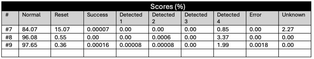
During testing, the injected glitches produced a variety of observable effects. We classified the results into the following categories:
Normal: The glitch had no observable effect on chip behavior.
Reset: The glitch caused a system crash or full reset.
Success: The loop counter was altered, but no glitch detectors were triggered.
Detected 1–4: The loop counter was altered, and one to four glitch detectors were triggered, respectively.
Unknown: The device printed unexpected characters, suggesting some level of corruption.
Error: Any other unclassified or abnormal behavior.
The following sections summarize the results of the fault injection characterization campaigns, organized by glitch detector sensitivity level.
At this lowest sensitivity level, the glitch detectors are effectively disabled – they seemed to not be functional and could not be triggered. This allowed us to focus purely on the CPU’s sensitivity to glitches without interference from detection mechanisms.
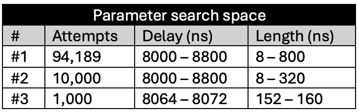
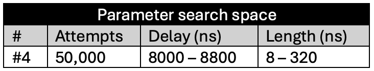
We conducted three separate FI campaigns at this level, progressively narrowing the glitch parameters (e.g., delay and length) to identify the most effective combinations.
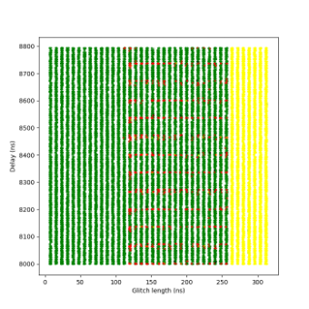
Figure 8 shows the plots of the glitch results. A clear boundary is visible between the green and yellow zones: this is where the glitch becomes too long or powerful, consistently crashing the target. The red points appear along this boundary, but only at specific delay values – those that align precisely with the execution of the instruction that when glitched breaks the loop. This correlation provides strong insight into the CPU’s timing sensitivity and the ideal glitch injection window. The highest success rate achieved was almost 14%.
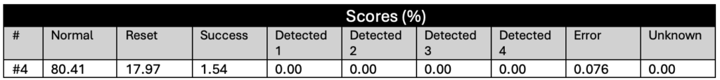
At this sensitivity level, the glitch detectors were still unable to detect any of the injected glitches. The results were largely indistinguishable from those observed at Sensitivity Level 0.
Due to the lack of significant behavioral differences, only a single short campaign was conducted at this level to confirm the similarity. No glitches were detected, and successful fault injections continued to occur under the same timing and voltage conditions as before.
Figure 9. Sensitivity level 1 – Campaign #4
The following tables summarize the results for this campaign:
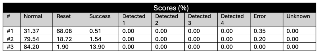
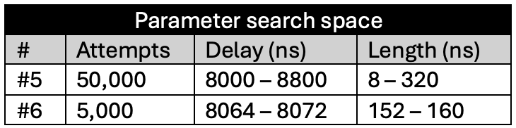
This is the first sensitivity level at which the glitch detectors were successfully triggered by our fault injections. However, it was still relatively easy to bypass the detectors under certain conditions.
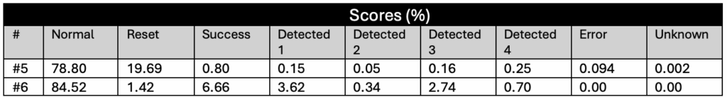
In the plot shown in Figure 10, additional colors indicate the number of detectors triggered during successful glitches – that is, glitches that broke the loop logic but:
Blue: 1 detector was triggered
Magenta: 2 detectors were triggered
Cyan: 3 detectors were triggered
Purple: All 4 detectors were triggered
To improve clarity, a second version of the plot is included, where green (normal glitches) and yellow (reset events) have been removed, making it easier to focus on detection behavior.
Figure 10. Sensitivity level 2 – campaign #5
A success rate of nearly 7% was achieved in this campaign – relatively high, considering this was the third level of sensitivity. These results suggest that while detection is now functional, the protection can still be bypassed with a well-timed and well-parameterized glitch.
The following tables summarize the different campaigns conducted at this sensitivity level and their respective outcomes.
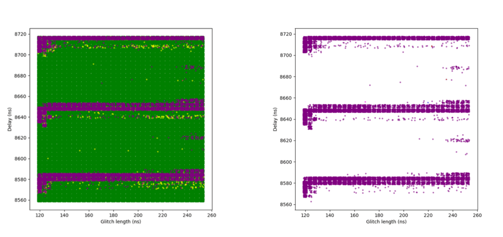
At this highest sensitivity level, the glitch detectors become very effective. Although we were still able to achieve some successful glitches, the success rate dropped significantly.
An initial campaign using broader parameters resulted in a small number of successful glitches. A second campaign attempted to narrow the parameter range based on what had worked at Sensitivity Level 2 but yielded no successful results. In hindsight, this was likely due to insufficient glitch attempts.
A third and final campaign expanded the narrowed parameter range slightly and achieved a modestly improved success rate. However, even then the rate was only about 0.0002%, indicating that the detectors are highly effective at this level.
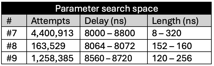
One interesting observation is that while at Sensitivity Level 2, many glitches triggered only one, two, or three detectors, at Sensitivity Level 3, glitches almost always triggered all four detectors.
The following plots show the two campaigns with broader parameters. In the right-hand plots, green and yellow dots are removed to better highlight successful red points.
Figure 11. Sensitivity Level 3 – Campaign #6
Figure 12. Sensitivity Level 3 – Campaign #8
Additional campaigns (not included in this article) attempted to further refine parameters around previously successful glitches, but did not yield any improvement in the success rate.
The following tables summarize the results for the three campaigns conducted at this sensitivity level.
Our experiments demonstrate that the RP2350’s glitch detectors are highly effective – but only when configured at the highest sensitivity level. At Sensitivity Levels 0 and 1, the detectors provided no meaningful protection. Sensitivity Level 2 reduced the success rate significantly, but not enough to prevent a fault injection (FI) attack (almost a 7% success rate).
Even at Sensitivity Level 3, it was still possible to glitch the RP2350, albeit with a very low success rate of approximately 0.00016% – or roughly one successful glitch every 625,000 attempts. Given that our setup could inject glitches at around 30 attempts per second, this translated to an average attack time of under six hours to achieve a successful result.
However, it’s crucial to place these results in context to properly evaluate the real-world risk of using the RP2350 in a security-critical application.
All experiments were conducted under ideal lab conditions:
Full control over the target
Precise and reliable trigger signals
Fast reset cycle
A test application that executes the vulnerable instruction repeatedly, every few clock cycles
These ideal conditions greatly increased our odds of success. In contrast, a real-world attack would face substantial challenges:
Limited or no access to CPU internals
Unreliable or noisy trigger sources
Potentially long and variable reset/restart times
Application code that executes sensitive operations infrequently or unpredictably
Introducing software countermeasures – such as instruction-level redundancy or random delays – would further reduce the success rate, often requiring multiple or perfectly timed glitches. Under such constraints, an attacker may require several months to mount a successful attack using crowbar-based glitching alone.
In future articles, we’ll explore whether the same conclusions hold for other glitching techniques, such as DAC-generated glitches or electromagnetic fault injection (EMFI).
Note: The winners of the Raspberry Pi Pico 2 challenge have shown that crowbar glitching the RP2350 can be much easier under specific conditions:
– Aedan Cullen successfully attacked the USB_OTP_VDD rail – a power domain not monitored by the glitch detectors.
– Marius Muench targeted the main VCC rail. However, as of this writing, no public information has been released about his glitching method or achieved success rate.
WHITEPAPER | July 29, 2025
Windows 11 Upgrade – The Hardware Security Focused Refresh
By
IOActive
Windows 10’s End of Life (EoL) is slated for October 14th, 2025. After this date, it will no longer be supported, and businesses are expected to upgrade to Windows 11; however, this upgrade is entirely unlike previous Windows upgrades in that strict hardware requirements are needed to support Windows 11. The transition from Windows 10 to Windows 11 represents a major inflection point for enterprise IT and SecOps, the hardware requirements are there to help with overall cybersecurity, as Windows moves from a primarily software security model to a best-of-both-worlds hardware and software model. In this blog post we discuss in detail the benefits of such upgrade through Intel vPro®. This work is part of the research IOActive published in a recent white paper, which was commissioned by Intel®.
IOActive works closely with both Microsoft and silicon security vendors. In this blog post, we focus on how PCs powered by Intel® Core™ Ultra processors and Intel vPro® offer a compelling strategy for Windows 11 upgrades.
Understanding the Evolution of Security Models from Windows 10 to Windows 11
Windows 10 was launched in 2015 with a comprehensive software-based security feature list,[1] including Windows Defender Antivirus, Windows Firewall, and data encryption technologies like BitLocker. However, software-based solutions can only take you so far in protecting data and systems and can still be vulnerable to sophisticated malware, zero-day attacks, and other Advanced Persistent Threats (APTs).
Windows 11, shifts focus from software-only to a best-of-both-worlds software-and-hardware-based security solution.[2] Providing a more robust, tamper-resistant security posture, helping ensure “secure by default” and “secure by design” principles.
Modern Copilot+ PCs, such as those powered by Intel Core Ultra Processors (200v Series), are built with security at their foundational level. At the heart of this enhanced security is the Microsoft Pluton security processor. Enabled by default, Pluton is designed to protect sensitive assets like credentials, encryption keys, and user identities by isolating them from potential attackers, even if they gain full access to the system.
Taking this to the next level, Microsoft designed Secured-core PCs to provide an “On-By-Default” security for businesses and users to provide three core pillars of protection:
Protecting identities from external threats
Securing the operating system from malware
Defending against hardware and firmware attacks
To properly support these secure pillars, specific hardware security requirements are necessary.
To Standard and Beyond: The Essential Secured-core PC Hardware Security Requirements
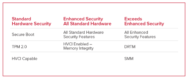
Microsoft Secured-core PCs are designed to provide an extra layer of protection against firmware, hardware, and software attacks offering three tiers of protection
Standard Hardware Security
These baseline security features are essential for SecOps teams aiming to reduce attack surfaces and ensure system integrity:
Secure Boot to block malicious code during startup.
To meet the enhanced hardware security requirements, all of the standard hardware security features must be enabled as well as HVCI.
HVCI enabled, enforcing runtime code integrity to block advanced exploits
Exceeds Enhanced Security
For organizations with high security requirements, these advanced capabilities offer deeper resilience:
Dynamic Root of Trust for Measurement (DRTM) to verify integrity during the boot process.
System Management Mode (SMM) Protection to isolate critical system functions from the OS.
This multi-tiered model helps enterprises align endpoint protections with their specific risk profile and compliance needs.
Inside Intel vPro
Intel vPro systems are built for enterprise environments requiring robust security, high performance, and strong manageability. They deliver over 30 hardware-enabled protections that extend Windows 11’s security model,
01. Out of Box – Security at First Boot
Every Intel vPro-based system with Windows 11 ships with essential security features pre-enabled. This “secure by default” approach ensures rapid deployment without sacrificing protection,
02. Intel vPro Surpasses Microsoft Secured-core PC L3 Requirements
Intel vPro goes beyond even the higher requirements of Secured-core PC, with additional security features and services to help SecOps teams with the deployment and support of their hardware fleet.
Intel Total Memory Encryption – Multi-Key (TME-MK) helps prevent data exposure from physical memory attacks..
Intel Virtualization Technology – Redirect Protection (VT-rp) Strengthens isolation in multi-tenant and hybrid environments.
Intel Threat Detection Technology (TDT) Provides AI-driven detection of advanced threats like ransomware..
Intel Active Management Technology (AMT) – BSOD Recovery Enables remote remediation even after crashes..
Intel Innovation Platform Framework (IPF) – Device Discovery offers real-time visibility into device configurations and status.
Deploying Intel vPro-based systems with Microsoft Pluton on Windows 11 ensures your business is not only compliant but also strategically prepared for tomorrow’s cybersecurity challenges. This is more than just protection; it’s long-term operational resilience.
03. Third-Party Assessed for Compliance
These capabilities are third-party validated against compliance standards such as NIST SP800-193, SP800-147, and SP800-155, easing audit and certification processes for industries like healthcare, finance, and government.
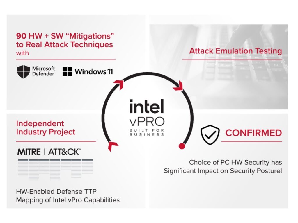
04. Industry Driven Validation Earlier this year, in collaboration with Microsoft, CrowdStrike, and AttackIQ, Intel mapped and ranked the hardware-optimized software security features against MITRE ATT&CK framework using the full set of Intel vPro security protections, some 30 hardware features, on a typical enterprise security software stack. This provided, in total, 90 hardware mitigations against real-world attacks when using Windows 11 and Windows Defender.
05. Achieve Enterprise-Class Security Posture
Together, Intel vPro and Pluton form a layered defense strategy that empowers IT leaders to confidently enforce zero-trust architectures, ensure business continuity, and scale securely in hybrid or cloud-native environments.
Conclusion
Upgrading from Windows 10 to Windows 11 is more than a user experience refresh, it’s a strategic opportunity to modernize your organization’s security architecture. With built-in protections Windows 11 sets a new baseline for device security.
For enterprises, the transition brings a clear advantage: by pairing Windows 11 with Intel vPro, organizations can go beyond compliance and exceed Secured-core PC requirements with hardware-enhanced capabilities like Intel TME-MK, Intel VT-rp, Intel TDT, and Intel AMT. These features offer operational benefits for SecOps teams, from accelerated recovery and advanced threat detection to improved device visibility and remote manageability.
This transition offers a rare out-of-the-box uplift for security and IT teams, delivering stronger protection without the complexity of traditional large-scale security projects.
Accelerating Threat Assessment in Vehicle ECUs | A TARA Case Study
By
IOActive
A global automaker required a thorough, but time-constrained, threat assessment and remediation plan for its critical Gateway Electronic Control Unit (ECU). The assessment needed to cover not only the main ECU but also its networked interaction with all of the vehicle’s numerous ECUs.
Having attempted to perform the assessment on its own, the manufacturer found its initial results lacked sufficient technical depth and were taking too long to report, threatening other key project timelines. They turned to IOActive to not only improve but also to accelerate the assessment process for this product.
The Challenge
An automotive Gateway ECU acts as a hub, routing and securing communication between ECUs and back-end services, such as the engine, transmission, brakes, steering, and infotainment. However, because it sits atop the vehicle’s digital nervous system, any compromise of the Gateway ECU can cascade to other subsystems through the entire in-vehicle network, including the Controller Area Network (CAN) bus and newer technologies like vehicular Ethernet. This widespread connectivity amplifies the potential for catastrophic results if vulnerabilities are exploited. Ensuring that any conceivable threats are accounted for and prioritized for remediation is a critical step in overall vehicle safety in the modern era.
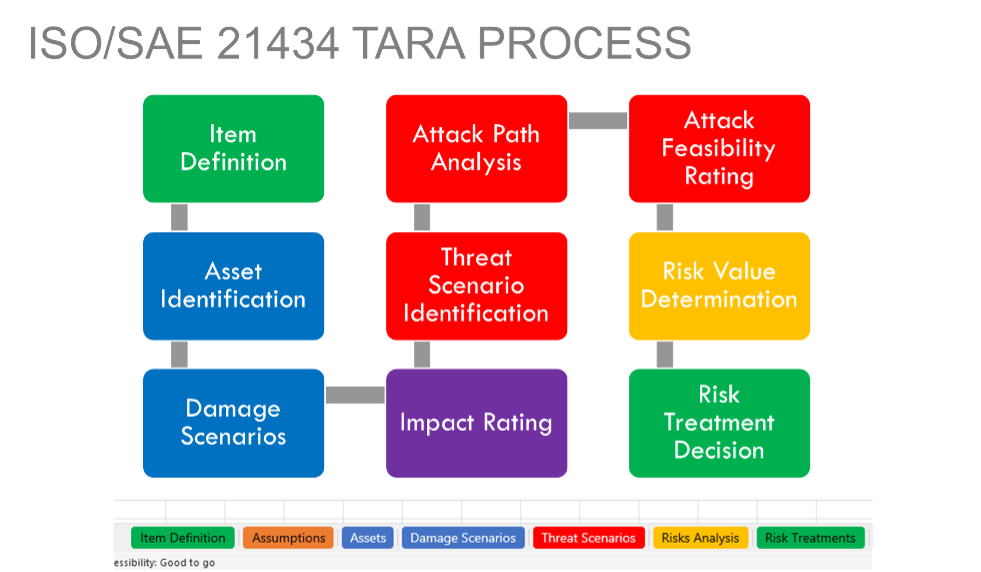
In this case, the automaker was looking to certify the reliability and security posture of its Gateway ECU in accordance with ISO/SAE 21434, the international standard that specifies requirements for cybersecurity risk management in the design and development of automotive systems. The purpose of ISO 21434 is to establish a comprehensive framework for managing cybersecurity risks throughout the entire lifecycle of a vehicle, and ensure that automotive systems are designed with cybersecurity in mind from the outset, continually addressing potential vulnerabilities and threats.
ISO 21434 applies to all stages of a vehicle’s lifecycle, including concept, development, production, operation, maintenance, and decommissioning. It covers all electronic and electrical systems within the vehicle, including software, hardware, and communication interfaces.
Enter TARA
A critical component of ISO 21434 is a risk assessment process known as Threat Analysis and Risk Assessment (TARA). A TARA’s risk-based approach involves systematically identifying potential damage scenarios, threat scenarios, and attack paths, evaluating their impact and attack feasibility, and determining the risk to decide appropriate mitigation strategies.
Given their tight project timelines, what the automaker needed was a specialized consulting service with core competencies focused on the use of TARA in an automotive system. That’s where IOActive comes in, as a research-driven security services company with a history of automotive testing and ethical hacking that dates to the earliest days of digital vehicle control systems.
In the context of automobile control systems, a meaningful TARA program is structured to ensure all potential security risks are identified, assessed, and prioritized for mitigation. Potential vectors include physical threats (when a malicious actor has hands-on access to a vehicle, for example) and wireless threats (for hacking attempts leveraging the vehicle’s on-board cellular and WiFi connectivity).
For this automaker client, IOActive organized the highly technical TARA to include the following tasks.
Initiation and Planning
Defining scope: Clearly outlining the scope of the TARA, specifying which systems, components, and interfaces related to the vehicle Gateway ECU are to be included.
Establishing objectives: Setting the goals for the TARA, such as agreeing on impact rating, attack feasibility, and risk calculation details, understanding the client’s concerns or key areas of focus, and establishing initial assumptions about the item along with the process for confirming and documenting any assumptions needed during the execution of the TARA.
Assembling the team: Forming a multidisciplinary team with expertise in cybersecurity, automotive systems, threat modeling, TARAs, software, hardware, and relevant regulatory standards (e.g., ISO 21434).
Asset Identification (Section 15.3)
Discovery: Determining and defining critical assets within the item, by reviewing the software modules, hardware components, data flows, dependencies, and communication interfaces.
Damage scenarios: Determining if a compromise of a cybersecurity property of any asset would cause some form of harm to the road user.
Threat Scenario Identification (Section 15.4)
Identifying threat sources: Cataloging potential sources of threats, such as external attackers, malicious insiders, and natural events.
Enumerating threat scenarios: Developing threat scenarios to describe how each identified damage scenario can be exploited in the item.
Impact Rating (Section 15.5)
Impact analysis: Evaluating the potential impact of each damage scenario on the vehicle’s safety, as well as financial, operational, and privacy impacts. This includes both direct and indirect consequences.
Attack Path Analysis and Attack Feasibility Rating (Section 15.6 and 15.7)
Attack path generation: Building a series of steps that could be used to realize a threat scenario that would result in damage. The standard doesn’t specify how this is done, but IOActive breaks attack paths into the following steps:
Primary Attack (Intrusion Vector)
Secondary Attack (Escalation Vector)
Tertiary Attack (Lateral Movement Vector)
Final Attack (Exploitation Phase)
Attack Feasibility Rating: Assessing the likelihood of each attack path occurring based on factors such as existing security measures, ease of exploitation, and known attacker capabilities
Risk Value Determination (Section 15.8)
Risk scoring: Assigning risk scores to each valid attack path based on the combined assessment of impact and attack feasibility. This helps prioritize the threats.
Risk categorization: Categorizing the risks into different to help facilitate the client’s risk treatment decision-making.
Risk Treatment Decision (Section 15.9)
Developing mitigation strategies: Proposing specific measures to mitigate the identified risks. This can include technical controls (e.g., encryption or authentication), process changes (e.g., regular security updates), and organizational measures (e.g., training or policy changes).
Residual risk assessment: Guidance on assessing the residual risk after implementing the mitigation measures to ensure that risk is reduced to acceptable levels.
Documentation and Reporting
Comprehensive documentation: Maintaining detailed documentation of the TARA process, including all damage scenarios, threat scenarios, and steps that form attack paths.
Reporting: Preparing reports for key stakeholders that summarize the findings, any actions taken, proposed future actions for the client, and the item’s current security posture.
The Assessment in Depth
Adhering to this systematic implementation of the TARA methodology, IOActive’s security consultants began with the detailed documentation review required to expose potential attack vectors that malicious actors could exploit. This process is much like a threat model, in which. our team identified potential risks and lack of controls, ranging from weak encryption practices to inadequate access controls and insecure communication protocols. Each weakness was examined in depth to help identify areas of potential risk to vehicle functionality, safety, and privacy.
Over the course of the two-month TARA process, IOActive’s automotive security team discovered multiple high-impact risks:
The automaker’s control systems did not currently support intra-ECU authentication and authorization. These missing controls could allow an attacker to wreak havoc across multiple vehicle systems based on a single compromise of a lower-value component.
The vehicle’s communications and control networks also lacked appropriate segmentation, which, like the authentication and authorization issue, could facilitate an attack on multiple ECUs from a single point of compromise.
Access to the cryptographic material used by the ECU was poorly understood and documented. This has the potential to complicate the assessment of system impact and identification of compromised keys in the event of an attack.
Throughout the course of the TARA engagement, IOActive’s expert consultants kept in constant contact with the client, asking probing questions about development and architecture that spurred the automaker’s own technical team to revisit core component security questions — and consider strategic changes to its products — with company decision makers.
The Results
IOActive completed the TARA within an impressive two-month timeframe, delivering results that surpassed those typically achieved by internal teams or other vendors. Leveraging our extensive experience across a diverse range of vendors and OEMs, IOActive provided the automaker with a detailed, realistic, and actionable roster of risks, each analyzed with significant technical depth and prioritized by practical risk level. Our experts’ broad spectrum of exposure enables a more thorough and insightful threat assessment, helping to ensure that potential security gaps are not overlooked.
The findings included not only proposed mitigation strategies but also an evaluation of their expected effectiveness in addressing each identified security gap. This comprehensive report offered the client a robust set of risks specific to their gateway ECU and a clear roadmap for mitigating them efficiently. Additionally, the TARA conducted by IOActive was a crucial step towards achieving ISO 21434 compliance, reinforcing the vehicle’s overall security posture with unmatched precision and speed.
Guest blog by Urban Jonson, SERJON with John Sheehy and Kevin Harnett
During my recent presentation at ESCAR USA, I shared findings from my latest research on the automotive industry’s adoption of Threat Analysis and Risk Assessment (TARA) processes to develop cybersecurity artifacts that align with regulatory requirements. The automotive TARA is a systematic process used to identify potential cybersecurity threats to vehicle systems, evaluate their likelihood and impact, and determine appropriate mitigations to reduce risk to acceptable levels.
One key insight derived across numerous TARA exercises is that many organizations struggle with consistency and accuracy in their internal cybersecurity documentation. To address this, I recommend thoroughly analyzing the workflows involved in creating, reviewing, and approving such documentation. By applying business process reengineering principles and best practices, organizations can streamline and strengthen these workflows.
These findings also highlight a broader pattern that we have observed across the gamut of industries, from automotive to energy to software development, and all points in between.
In our experience working with companies of all sizes and types, one challenge keeps coming up: cybersecurity operations are becoming more expensive, but not necessarily more effective. Too often, we see teams overwhelmed by alerts, buried in redundant tools, and unsure whether their efforts are aligned with real threats. If this sounds familiar, there’s a better way to approach it—one that blends deep knowledge of threat behavior, innovative process design, and focused spending. And yes, sometimes it means bringing in an outside perspective like ours to get things moving in the right direction.
Starting with Real Threat Intelligence: TTPs
When we start working with a company, one of the first things we look at is how well its cybersecurity efforts align with actual risks. We use industry-specific TTPs—Tactics, Techniques, and Procedures used by real attackers in that sector—to uncover what’s really at stake. For example, in finance, phishing and credential theft are huge; ransomware targeting OT environments is more common in manufacturing.
This isn’t just threat modeling, it’s about making sure the company’s cybersecurity operations are focused on what matters. We’ve seen companies spend big on fancy cybersecurity tools that protect against unlikely scenarios, while overlooking common, costly vulnerabilities. TTPs help us steer the conversation toward high-impact areas that deserve real attention.
Reengineering Cyber Processes That Drag Companies Down
With those threat patterns in mind, we conduct a process analysis to map the way cybersecurity workflows actually operate inside the business. Are patching cycles too slow? Are incidents managed the same way across departments? Are cybersecurity tools overlapping or underutilized?
This is where business process reengineering comes in. We work with teams to strip away complexity, redesign inefficient workflows, and introduce automation or clear accountability where needed. The goal is simple: make the company’s cybersecurity operations faster, smarter, and cheaper without compromising protection.
And we get it—internal teams are often too close to the process to spot the friction. That’s why companies bring us in. We bring an external lens, ask the hard questions, and get everyone aligned on a working strategy.
The Eisenhower Matrix: A Surprisingly Useful Budget Tool
Once we’ve got processes in better shape, it’s time to review technology spending. One of the tools we like to use is the Eisenhower Matrix, which enables us to categorize every cybersecurity investment:
Urgent and Important: Must-haves, like tools protecting your most targeted assets
Important but Not Urgent: Strategic efforts, like employee training or improving logging infrastructure
Urgent but Not Important: Fire-drill requests that burn budget but add little value
Neither Urgent nor Important: Legacy tools collecting dust (and invoices)
This simple framework helps leadership make clearer, faster decisions, and we help drive those conversations with data and context.
Why Bringing in a Consultant Helps
You might wonder, “Why bring in an outside firm to do this?” The answer is that a security consultancy with seasoned experts offers speed, experience, and perspective. We’ve worked with multiple industries, seen common patterns and pitfalls, and can move faster than most internal teams alone. We’re not here to replace your cybersecurity team; our job is to make them more effective.
If you’re serious about reducing costs, boosting productivity, and ensuring your cybersecurity efforts match your business needs, let’s talk. A little outside perspective might be just what your company needs to move forward with clarity and confidence.
Urban Jonson is a co-founder of SERJON (www.serjon.com) and a frequent collaborator with IOActive. Urban is a cybersecurity industry leader and serves in multiple advisory roles, including SAE International, TMC, ESCAR USA, CyberTruck Challenge, and as a cybersecurity expert for FBI InfraGard and the FBI Automotive Sector Working Group.
INSIGHTS | June 3, 2025
Better Safe Than Sorry: Model Context Protocol
By
Mohamed Samy
In this blog post, we’ll delve into the world of the Model Context Protocol (MCP), an open standard designed to facilitate seamless integration between AI models and various data sources, tools, and systems. We’ll explore how its simplicity and widespread adoption have led to a proliferation of servers without basic security features, making them vulnerable to attacks.
Our goal is to raise awareness about the critical need for mandatory authentication in the MCP protocol, and we believe that this should serve as a wake-up call for other standards to follow suit.
The Model Context Protocol: A Primer
The MCP follows a client-host-server architecture, built on JSON-RPC using two transport mechanisms:
Sub-process, using Standard Input and Output,
Independent process, using streamable HTTP or Sever-side Events (SSE).
The protocol standard’s simplicity coupled with its de facto compatibility with existing open- and closed-weight Large Language Models (LLMs) made it an instant hit, with widespread adoption from the open-source community and almost all leading LLM trainers.
As of version 2024-11-05, the MCP standard has already been used in over 4800+ MCP server implementations, according to the MCP.io website. Unfortunately, this version didn’t include an authorization mechanism in its specification, even though the draft version included it as an optional feature.
By design, the MCP protocol standard mandates servers to publish three fundamental building blocks:
Prompts
Resources
Tools
From a client perspective, these three primitives represent:
System Instructions
Data Access
Function Execution
However, from a malicious perspective, the same three primitives represent:
Information Leakage
Data Exfiltration
Remote Command Execution
As an example of this, Invariant Labs recently published a new MCP attack vector called Tool Poisoning Attacks, which utilizes the three primitives at once to achieve critical vulnerabilities on the host system.
In this attack, the MCP server itself acts maliciously, and as previously mentioned, it is unauthenticated by design, so this will end up as a “wild west” of emerging attack vectors across all AI-integrated systems or services.
A Test Case
To test the impact of such specifications firsthand, we created the following Docker Compose environment. (Note that some information is intentionally redacted to avoid fingerprinting the MCP implementor.)
We simply ran docker-compose up then fired up MCP Inspector:
This immediately shows us that we can connect to and use the MCP Server without authentication at all:
Additionally, this specific MCP Server provides a tool that executes SQL queries against the Postgres database as functionally expected.
This means we are one step away from exposing our entire database externally by not changing the listening hostname.
The important question here is: Are we ahead of the curve in terms of MCP security or not?
A Quick Exercise: Searching for MCP Servers
To answer the question above, we performed a quick exercise.
We used Grep.app to search GitHub public repositories for MCP servers’ common HTTP headers.
We used these headers as search queries on Shodan.
Bingo!
We discovered two hosts with a public MCP server over HTTP protocol. One of them was already flagged as “compromised” from Shodan, and the other one was publishing n8n, Open WebUI and even Ollama Web Applications before it was apparently taken down.
It is worth noting that Ollama servers – just like MCP servers – are unauthenticated by default and have already had their fair share of remote code execution vulnerabilities (CVE-2024-37032).
The Takeaway: Mandatory Authentication for MCP
In conclusion, we believe that authentication is a mandatory requirement for any standard that involves remote execution of code or sensitive data access. The MCP protocol should require authentication to prevent implementors from claiming full specification compliance while omitting authentication altogether. This will help prevent insecure deployments and ensure the integrity of AI-integrated systems and services.
As the MCP protocol continues to gain traction, we hope this blog post serves as a wake-up call for the community to prioritize security and adopt mandatory authentication.
INSIGHTS | May 20, 2025
IOActive Autonomous and Transportation Experience and Capabilities
By
Kevin Harnett
AUTONOMOUS AND REMOTE CONTROLLED/ACCESS TECHNOLOGY
For the past 5 years, IOActive has been focused on understanding Autonomous and Remote-Controlled/Access technologies and their inherent vulnerabilities and possible impacts to Functional Safety. IOActive consultants assume the posture of real-world attackers, attempting to bypass existing security controls and gain access to connected systems or services, or to the vehicle itself.
Transportation technology is evolving significantly, with enhanced autonomous functions revolutionizing automobiles, commercial trucks, agriculture equipment. AI and Machine Learning (AI/ML) are fundamentally transforming Autonomous Vehicles by enabling them to understand road conditions, identify objects, predict traffic flow, make real-time decisions, and predict potential hazards, paving the way for partial and fully autonomous driving. IOActive delivers a suite of services that cover every facet of AI and ML security offerings which are built on proven methodologies (i.e. Threat Modeling/Architecture Review, AL/ML code review/Vulnerability Assessment, Application/Device Penetration Testing, and AI Infrastructure Security, for more information. https://www.ioactive.com/service/ai-security-services/). As vehicles have become connected, this connectivity provides significant benefits and presents significant cybersecurity risks and vulnerabilities.
Two other emerging vehicle technologies that are now prevalent in today’s connected world are Telematics (i.e. automobiles, commercial trucks, agriculture/mining vehicles, and sea cranes) and Electric Vehicle Supply Equipment (EVSEs) and both have remote cloud infrastructures which increases the cybersecurity risks for attacks and vulnerabilities, such as: weak/unencrypted communications, over-the-air (OTA) firmware attacks, insecure APIs, and weak/vulnerable cloud services.
For over a decade, IOActive has been a pioneer in Transportation cybersecurity research, with a proven track record and experience in conducting penetration and security assessments on autonomous vehicles and remote-controlled assets, such as:
Automobiles – ADAS (Level 2 and 3), Robotaxis, Telematics
Commercial Trucks – Autonomous Trucks
Electric Vehicles – EVSEs
Agriculture – Autonomous Agriculture Vehicles and Autonomous On-Road/Off-Highway Vehicles (OHV)
Autonomous shuttles – Personal Rapid Transit (PRT) vehicles
A core focus of our transportation cybersecurity research program has been to help industry stakeholders with empirical vulnerability data to make risk-informed decisions about threats to cyber-physical systems. Table 1 summarizes our experience and provides examples of our recent Autonomous and Remote-Controlled/Remote Access projects conducted by IOActive over the past 5 years:
IOACTIVE TRANSPORTATION CYBERSECURITY RESEARCH
IOActive is the leading transportation cybersecurity firm, investing heavily in primary research and working with OEMs, suppliers, and academia to understand the risks, threats, and business impacts facing the transportation industry. IOActive leverages this body of research to provide clients with deeper assessments and superior guidance to leverage innovative new technologies while developing safer and more secure data, vehicles, and infrastructure. Table 2 depicts several sample research papers and articles published by IOActive regarding the Transportation Sectors and the links are below:
Transportation cybersecurity compliance refers to the measures taken by transportation providers to ensure their systems and data are protected from cyber threats, while also adhering to regulatory and industry standards. This includes implementing security controls, reporting incidents, and conducting vulnerability assessment. Transportation organizations must comply with cybersecurity rules and regulations set by agencies like the TSA, DHS, UNECE, ISO/SAE, EU Commission, FAA, EASA, Coast Guard, International Association of Classification Societies (IACS) and IEC. The table below describes for each transportation sector the applicable Cybersecurity Standards, Risk Assessment Methodologies, Information Sharing and Analysis Center (ISACs), and Communications Protocols.
Table 3 describes for each transportation sector the applicable Cybersecurity Standards, Risk Assessment Methodologies, Information Sharing and Analysis Center (ISACs), and Communications Protocols.
IOACTIVE CYBERSECURITY SERVICES
To help protect your business from today’s increasingly complex and sophisticated cybersecurity risks, IOActive offers a full range of cybersecurity services, including penetration testing, full-scale assessments, secure development lifecycle support, red team and purple team engagements, AI/ML security services, supply chain integrity, code reviews, security training, and security advisory services. Learn more about our offerings at https://www.ioactive.com/services.
To learn more about IOActive’s Connected Vehicle Cybersecurity Services, click here.
At IOActive, we have penetration testing and full stack assessment skills that span all the transportation sectors and specifically, we have unique cybersecurity knowledge and capabilities regarding autonomous technologies. If you’re interested to learn more about how we can help, contact us and one of our transportation cybersecurity specialists will be in touch.